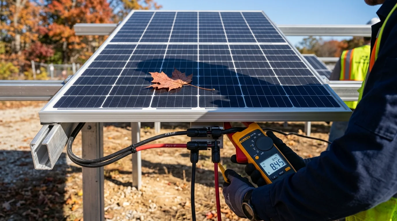
Few scenarios in solar engineering confound beginners more than the dramatic impact of partial shading.
If a 400-Watt solar panel has 72 silicon cells, logic suggests that shading one single cell with a fallen tree leaf should only reduce output by approximately , or about 1.4%.
Yet in the field, when that single leaf settles onto the lower edge of the glass, the solar generator’s LCD display suddenly collapses:
A tiny leaf covering less than 2% of the panel’s physical surface area has wiped out 50% of the entire system’s electrical power.
This is not a defect or manufacturing glitch. It is the fundamental consequence of series circuit physics, reverse-bias breakdown, and internal bypass diode protection.
Because solar cells are wired in series like a kinked hose, shading one single cell bottlenecks current across that entire series sub-string. To prevent destructive reverse-bias hot-spot fires, internal bypass diodes activate in the junction box, routing current around that cell group. This immediately sacrifices 33% of the panel’s voltage and distorts the power curve into multiple false peaks, causing low-cost MPPT charge controllers to lose 33% to 60%+ of total array wattage.
Circuit Physics: The Series String Garden Hose Analogy
To understand why partial shading is catastrophic, we must inspect the electrical wiring inside a photovoltaic module.
A typical 400W residential or commercial solar panel contains 60 to 72 individual solar cells. Each individual monocrystalline silicon wafer produces roughly to of DC potential under direct sun. To produce a usable operating voltage (around to ), all of these individual cells are wired in series:
According to Kirchhoff’s Current Law (KCL), the electrical current flowing through any series circuit must be identical at every single point:
Photocurrent generation inside silicon is strictly proportional to direct photon flux. An unshaded cell generates roughly . If an oak leaf falls onto a single cell, shading 80% of its surface, that cell can now generate only .
Because all cells are connected in series, that shaded cell acts like a severe kink in a garden hose: it throttles the entire series string down to .
Without protective circuitry, the other 71 unshaded cells would generate an enormous voltage potential (), attempting to force 10 Amps through the high-resistance bottleneck.
The Danger of Reverse Bias: Hot-Spot Thermal Runaway
When unshaded cells force current through a shaded cell, the shaded cell is driven into reverse bias. Instead of acting as a power generator, the cell becomes a resistive power consumer:
In a high-voltage string (such as panels connected in series to a home backup power station or high-voltage solar inverter), this localized dissipation can reach concentrated into a postage-stamp-sized area.
Under infrared thermography, this phenomenon—known as a hot spot—causes cell temperatures to skyrocket past to ( to ). Over time, hot spots:
- Permanently crack the silicon crystal wafer.
- Melt and brown the protective EVA polymer encapsulant.
- Burn through the backsheet, creating serious fire hazards.
How Bypass Diodes Work: Circuit Architecture
To prevent destructive hot-spot burning, panel manufacturers integrate Schottky bypass diodes inside the junction box on the rear of the panel.
A standard 60- or 72-cell module is typically divided into three internal sub-strings (typically 20 or 24 cells per group), with one bypass diode wired in anti-parallel across each group:

Figure 1: Internal bypass diode circuit operation. Under normal sun, diodes remain reverse-biased (inactive). When Cell B is shaded, reverse voltage turns on Bypass Diode B, diverting current around the blocked group and creating a multi-peak P-V curve.
Normal (Unshaded) Operation
Under full sunshine, all cells generate positive voltage. The cathode of each bypass diode is at a higher electrical potential than the anode. The diode is reverse-biased (turned OFF), allowing full forward current to pass through all series cells unimpeded.
Shaded Operation (Bypass Diode Activation)
When a cell in Sub-String B is covered by a leaf or shadow, its internal resistance spikes. The voltage across that cell group collapses into negative potential. Once the reverse voltage exceeds the forward conduction threshold of the Schottky diode (around to ), the diode turns ON (forward biased).
Current takes the path of least resistance: it flows around Sub-String B through the bypass diode, rejoining the circuit at Sub-String C.
The Engineering Trade-Off
- The Good News: Sub-String B is completely bypassed. Hot-spot heating is halted, and Sub-Strings A and C continue producing full 10-Amp current.
- The Bad News: Sub-String B’s voltage is removed from the array. If the panel’s normal operating voltage is , losing one-third of the cells instantly drops the panel output to .
The MPPT Dilemma: False Peaks and Tracking Trapdoors
The physical activation of a bypass diode does not guarantee that your solar charge controller will harvest maximum power. It introduces a software challenge known as multi-peak P-V curve distortion:
When all cells are evenly lit, the power-voltage (P-V) curve of a solar array has a single, smooth hill with one obvious Maximum Power Point (MPP).
When partial shading triggers a bypass diode, the P-V curve develops multiple local peaks (see Figure 1, right):
- Local Peak (High Voltage, Low Current): All three sub-strings active, but current is restricted to the shaded cell’s bottleneck ().
- Global Maximum Peak (Low Voltage, High Current): One sub-string bypassed, remaining two sub-strings running at full current ().
Why Cheap Charge Controllers Fail
Standard Perturb and Observe (P&O) algorithms in low-cost MPPT controllers only take small incremental steps along the voltage curve. If the controller starts tracking from open-circuit voltage (), it encounters the first local peak (72W) and stops, believing it has reached the summit!
Advanced charge controllers (found in commercial power stations and high-end hardware like Victron Energy) execute periodic Global Maximum Power Point Tracking (GMPPT) sweeps every 10 to 15 minutes, sweeping the entire voltage curve from zero to to lock onto the true global peak (review our benchmark comparison in MPPT vs. PWM Charge Controllers).
The Half-Cut Cell Revolution: How Modern Panels Mitigate Shading
If you have shopped for solar panels recently, you have likely noticed that virtually all modern modules (from brands like Canadian Solar, LONGi, Renogy, and EcoFlow) are described as “Half-Cut” or “Split-Cell” modules.
In a half-cut solar panel, standard full-square silicon wafers are laser-cut into two identical halves. A standard 60-cell panel becomes a 120 half-cut cell panel.
| Shading Scenario | Standard Full-Cell Panel Output | Modern Half-Cut Module Output | Active Bypass Diodes |
|---|---|---|---|
| Unshaded Baseline (1,000 W/m²) | 400 Watts (100%) | 400 Watts (100%) | 0 Diodes Active |
| Single Fallen Leaf (Bottom Edge) | 268W (-33% voltage loss) | 350W (-12.5% loss) | 1 Diode Active |
| Bottom 20% Shaded by RV AC Unit | 0W – 80W (-80% to -100%) | 200W (50% output preserved) | 3 Diodes (Bottom Half) |
| Narrow Tree Branch Across Entire Length | 40W (-90%) | 180W – 220W (~50%) | 2 to 3 Diodes Active |
Why Half-Cut Architecture Is Superior
- Twin-Parallel Sub-Array Design: A half-cut module is split internally into two independent twin halves (an upper sub-array and a lower sub-array) connected in parallel. If the lower half of the panel is shaded by an RV rooftop air conditioner, the upper half operates at 100% full power, guaranteeing at least 50% nameplate energy yield.
- 75% Lower Resistive Line Losses: Cutting the cell in half cuts the electrical current through each internal busbar in half (). Because resistive power loss follows the formula: Internal thermal resistance heating is cut by 75%, keeping cells cooler and boosting operating efficiency even in full sun (compare this with our flexible vs. rigid panel thermal analysis).
4 Field Rules to Defeat Shading Losses
When installing an off-grid solar array for a cabin, emergency backup battery, or mobile camper, use these four field-tested design strategies to prevent partial shade from choking your power:
Optimize Landscape vs. Portrait Orientation
Because internal sub-strings run lengthwise along a standard panel:
- If shade creeps vertically from the bottom (such as morning shade from a parapet wall or vehicle roof edge), install half-cut panels in portrait orientation. The lower half will be shaded while the upper half continues pumping clean power.
- If shade passes across horizontally (such as a utility pole or tree trunk), evaluate how the shadow line intersects the internal diode sub-strings.
Use Parallel Strings in Partially Shaded Locations
When wiring multiple solar panels together, remember that series wiring compounds shading vulnerability. If four 100W panels are wired in series and one panel is shaded, that single panel bottlenecks all four panels.
If you frequently camp under tree canopies, wire panels in parallel or series-parallel (2S2P). A shaded panel in a parallel branch only affects its own circuit, allowing the remaining parallel strings to deliver full power to the battery (see our full engineering guide on series vs. parallel solar wiring).
Leverage Independent Dual MPPT Ports
High-capacity solar generators like the Anker Solix F3800 and EcoFlow Delta Pro 3 feature dual independent MPPT controllers. Instead of combining all panels into one massive series array, connect the east-facing or shade-exposed panels to MPPT 1, and the unshaded roof panels to MPPT 2. The controllers optimize each sub-array completely independently.
Maintain the 10° Self-Cleaning Tilt Angle
Bird droppings and dried mud dams along the bottom aluminum frame create permanent, localized cell shading that keeps bypass diodes engaged continuously. Always maintain at least a 10° tilt angle to ensure rainwater cleans the glass face naturally (see our optimal solar panel tilt angle guide).
Frequently Asked Questions
Can bypass diodes wear out or fail?
Yes. Bypass diodes are silicon semiconductors that endure thermal stress whenever they conduct current. If a panel suffers from continuous partial shading every afternoon for several years, the diode remains in continuous forward conduction, dissipating heat inside the junction box. If a bypass diode overheats and fails in a “shorted” state, that one-third sub-string is permanently disabled, even in full midday sun.
Do microinverters solve solar panel shading?
Yes, exceptionally well. On residential rooftops, microinverters (such as Enphase) attach directly to the back of each individual panel, performing independent MPPT tracking for every module. If one panel is shaded by a chimney or tree branch, only that specific panel’s output drops, leaving the rest of the roof operating at 100% capacity. For portable power stations, using independent MPPT input ports achieves a similar isolation benefit.
How much power does a dirty solar panel lose?
A light uniform layer of road dust or pollen typically reduces total solar output by 3% to 7%. However, localized spot soiling (such as a concentrated bird dropping or a dried leaf) is far more damaging than uniform dust. Because the bird dropping completely blinds one or two cells, it activates a bypass diode, slashing module voltage by 33% and causing far worse energy loss than a uniform layer of dust.
Does bifacial solar gain help when the front is shaded?
Yes! If the front face of a bifacial ground-mount panel is partially shaded by a leaf or debris, high albedo light reflecting off white snow or light gravel strikes the rear cells. This diffuse rear irradiance provides sufficient reverse photocurrent to reduce hot-spot severity and mitigate the depth of the voltage drop.
What should I do if my solar generator shows zero watts under partial shade?
Check your charge controller’s minimum MPPT starting voltage. Many large power stations (like the EcoFlow Delta Pro or Bluetti AC300) require a minimum input threshold (e.g., 30V or 60V) before the charging circuit wakes up. If partial shading activates two bypass diodes, your panel voltage may collapse below the inverter’s minimum startup window, causing the solar generator to display 0 Watts entirely. Ensure your series string voltage remains comfortably above the controller’s minimum cutoff voltage even with two diodes active.