When connecting multiple solar panels to charge a portable power station or home battery bank, you face a fundamental wiring choice: Series or Parallel?
Connect them in series, and your system starts charging earlier in the morning and lets you use long extension cords. But let a single tree branch shade one panel, and your total output can collapse.
Connect them in parallel, and your system shrugs off shading. But your wiring amperage doubles or triples, risking heavy energy losses or triggering your power station’s internal current clipping threshold.
Below is the straightforward engineering breakdown of both wiring architectures, how to calculate voltage and current limits, and which setup is right for your specific gear.
Series wiring (connecting positive to negative) adds voltage while keeping amperage low. It is optimal for unshaded locations and long cable runs (30–100 ft) because high voltage minimizes resistive line losses (). Parallel wiring (using Y-branch splitters) keeps voltage low while adding amperage together. It is optimal for partially shaded environments and cold winter climates where high series voltage risks frying your MPPT controller’s maximum voltage ceiling.
1. Electrical Fundamentals: What Changes in Series vs. Parallel?
Assume you have two identical 200W solar panels with typical specifications:
- Voltage at Max Power ():
- Current at Max Power ():
- Open-Circuit Voltage ():
- Total Voltage ():
- Total Current (): Remains locked at
- Total Power:
- Cable Requirement: Standard 12 AWG extension wire.
- Total Voltage (): Remains locked at
- Total Current ():
- Total Power:
- Cable Requirement: Thick 10 AWG or 8 AWG wire to prevent heating.
2. Voltage Drop and Line Resistance: The Reality
Why do professional solar installers prefer higher voltages whenever possible? Resistive line loss.
Every copper cable has internal electrical resistance (). The amount of power lost as heat along your cable run scales with the square of the current:
Imagine running a 50-foot 12 AWG extension cable ( round-trip):
- In Series ( at ):
- In Parallel ( at ):
In parallel, four times more energy is lost as heat inside the cable. To run parallel panels across long distances, you must purchase thick, heavy 8 AWG or 10 AWG cables.
To learn how high-voltage DC is stepped down efficiently inside modern generators, see our guide on MPPT vs PWM solar charge controllers.
3. The Shading Problem: Why Series Strings Suffer
While series wiring wins on cable efficiency, it has an Achilles’ heel: partial shading.
Think of a series solar string like a single garden hose:
- Solar cells in series pass the same stream of electrons. If a tree branch or chimney shadow falls across just 10% of one panel, that shaded cell acts like a kink in the garden hose.
- The shaded cell becomes a high-resistance bottleneck, restricting current flow through every other panel in the entire series string.
- While modern panels have internal bypass diodes to route current around shaded cell groups, output still drops drastically.
In contrast, in a parallel array, each solar panel operates as an independent electrical branch. If Panel 1 is 50% shaded, it simply produces half its current. Panel 2 sits in full sunlight and continues producing 100% of its rated power unimpeded.
4. Power Station MPPT Limits: Voltage vs. Amperage Constraints
Before connecting your panels, check your portable power station’s solar input specifications. You will see two hard limits:
- Max Voltage Limit (e.g., 60V, 150V, or 500V DC):
- Absolute Hard Limit. If cold winter air spikes your series above this limit, it will permanently destroy the MPPT controller. Always verify winter voltage with our cold temperature Voc safety calculator or read our guide on cold weather Voc voltage spikes.
- Max Amperage Limit (e.g., 12A, 15A, or 25A DC):
- Soft Current Limit. If you wire panels in parallel and produce 20A, but your power station has a 12A current limit, nothing blows up. The MPPT controller safely draws its maximum 12A and leaves the excess current on the panels (known as overpaneling or current clipping).
5. Architectural Comparison Matrix
| Factor | Series Connection | Parallel Connection | Winner / Recommendation |
|---|---|---|---|
| Wiring Simplicity | Daisy-chain cables directly (+ to -). | Requires MC4 Y-branch connectors. | Series (Zero extra hardware) |
| Cable Efficiency (Distance) | High voltage minimizes line loss (). | High amperage generates wire heat and voltage drop. | Series (Best for 30–100 ft runs) |
| Partial Shade Tolerance | Poor: Shaded cell bottlenecks entire string. | Excellent: Panels operate independently. | Parallel (Best for trees / RVs) |
| Low-Light / Dawn Startup | Starts earlier: Voltage crosses battery threshold sooner. | Starts later: Lower voltage takes longer to trigger MPPT. | Series |
| Risk of Controller Burnout | High risk if winter cold spikes over limit. | Zero risk: Voltage stays safely low. | Parallel |
If you own a large home backup system capable of multi-channel high-voltage solar inputs (such as the 60V–150V dual MPPTs on the Anker Solix F3800), you can adopt a Series-Parallel hybrid (2S2P) configuration: wire two pairs of panels in series, then join those two pairs in parallel to get the best of both worlds.
Check Your Series Array Voltage
Input your panel count and cold weather temperatures to ensure your series string stays within MPPT limits.
Open Voc Safety Calculator →
6. Frequently Asked Questions
Can I mix different brands or wattages of solar panels together?
You should avoid mixing different panels whenever possible. If you wire a 100W panel (5A) and a 200W panel (10A) in series, the 200W panel will be throttled down to 5A, wasting half its capacity. If you wire different panels in parallel, their operating voltages must match within 5% to avoid backfeeding.
What are MC4 Y-branch connectors?
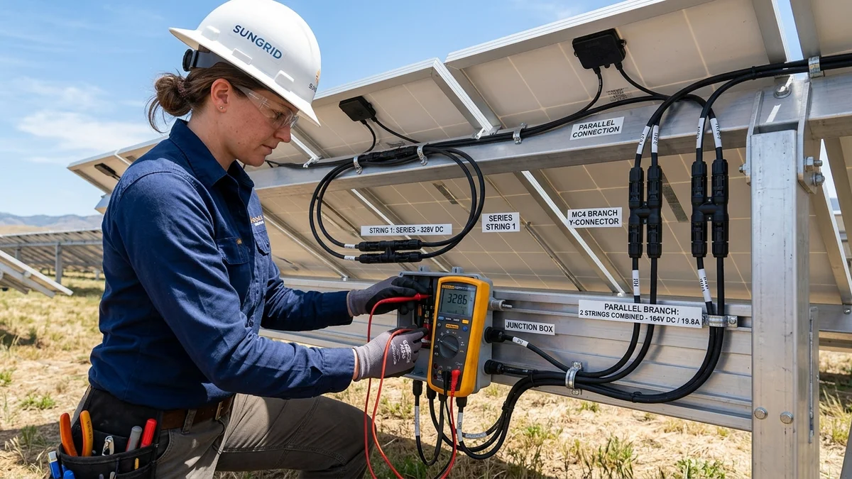
Y-branch connectors are specialized 2-to-1 solar adapters. They take the positive leads from two separate solar panels and merge them into a single positive cable, and do the same for the negative leads, putting the two panels in parallel.
Do I need inline fuses for parallel solar panels?
If you are wiring three or more panels in parallel, the National Electrical Code mandates an inline fuse on each positive string lead. If one panel develops an internal short circuit, the other panels could backfeed full current into the faulted panel, creating a fire hazard. For two panels in parallel, fuses are generally not required.