A modern portable power station or home battery backup system contains dozens of individual lithium cells linked in series and parallel. But lithium cells cannot safely self-regulate.
If a single cell inside a 16-cell series string charges to 3.75V while the others are at 3.35V, continuing to charge without intervention will permanently damage that high cell or trigger a protective shutdown.
Preventing this failure is the role of the Battery Management System (BMS). Below, we explain the circuitry behind active and passive cell balancing, how solid-state protection switches work, and how to troubleshoot common BMS lockouts.
A Battery Management System (BMS) is a specialized microprocessor board wired to every individual cell in a battery pack. It performs three critical jobs: Safety Protection (disconnecting charging/discharging if voltage, temperature, or current exceeds limits), Cell Balancing (equalizing voltage across all series cells to prevent capacity drift), and State of Charge Estimation (using precision shunt resistors to calculate remaining Watt-hours).
1. The Core Architecture of a Modern BMS
A standard 48V (51.2V nominal) LiFePO4 power station uses 16 cells in series (a 16S topology). The BMS is physically connected to every single junction point via balance sense wires:
Multi-channel analog front-end (AFE) ICs measuring cell voltages every 10 milliseconds, along with NTC thermistors monitoring core temperatures.
Banks of solid-state power MOSFETs or magnetic contactors that physically interrupt charge or discharge current within micro-seconds of a fault.
High-precision copper-manganin current shunt calculating micro-amp throughput to report accurate State of Charge (SoC) percentages to the display.
2. Why Cell Balancing is Mandatory
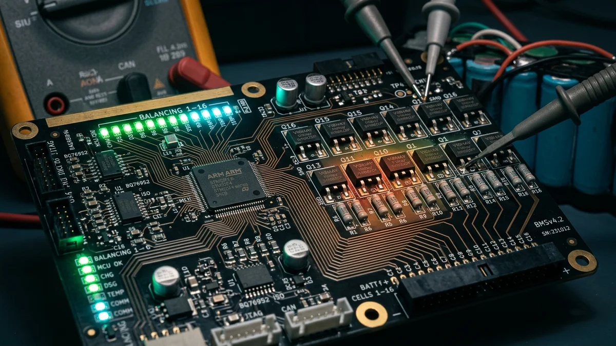
No two manufactured battery cells are 100% identical. Even in high-end automotive-grade cells, minuscule differences in chemical purity, internal resistance, and manufacturing tolerances cause cells to charge and discharge at slightly different rates.
The Danger of Cell Drift
Imagine a 4-cell (12.8V nominal) battery where three cells are at 3.35V and one runner cell is at 3.55V:
- As charging approaches 100%, the runner cell crosses the Over-Voltage Protection (OVP) limit () before the others have absorbed full charge.
- The BMS immediately cuts off charging to protect the runner cell.
- The result: The entire battery pack stops charging early, stranding the other three cells at 85% capacity. The user loses 15% of their total rated Watt-hours.
Passive vs. Active Balancing
- Passive Balancing (Standard): When charging and a cell exceeds a threshold (typically ), the BMS turns on a small transistor, routing excess current through a tiny surface-mount resistor (). The excess energy is bled off as gentle heat while lower cells catch up.
- Active Balancing (Advanced): Instead of wasting energy as heat, active balancers use capacitive or inductive circuits to shuttle electrons from high-voltage cells directly into lower-voltage cells.
To understand why keeping your pack within healthy voltage ranges matters for longevity, read our guide on the 80% DoD rule in LiFePO4 cells.
3. Critical BMS Protection Triggers
| Protection Event | Standard LiFePO4 Setpoint | BMS Response | Recovery Condition |
|---|---|---|---|
| Cell Over-Voltage (OVP) | 3.65V per cell | Disconnects charge circuit | Voltage drops below 3.45V |
| Cell Under-Voltage (UVP) | 2.50V per cell | Disconnects discharge circuit | Voltage recovers above 2.80V via charging |
| High Temperature (Charge) | > 113°F (45°C) | Cuts incoming solar / AC power | Core temp drops below 104°F (40°C) |
| Low Temperature (Charge) | ≤ 32°F (0°C) | Blocks charging completely | Cells warm above 41°F (5°C) |
| Short-Circuit Protection | Instantaneous current spike | Disconnects in < 200 microseconds | Manual load disconnection / reset |
(For a deep dive into sub-freezing charge risks, read our guide on cold weather lithium charging below 32°F).
4. Common BMS Failure Modes & How to Fix Them
- “Premature Shutoff at 15% Remaining”:
- Cause: A single weak cell hits the 2.50V Under-Voltage cutoff while the rest of the pack is still at 3.10V. The BMS triggers pack shutdown to prevent that cell from reversing.
- Fix: Perform a top-balance recalibration. Charge the unit with a low-wattage AC charge (e.g., 200W–300W) to 100%, and leave it plugged in for 6–8 hours to give the passive bleed resistors time to equalize cell voltages.
- “Unit Shuts Down Under High Inrush Surges”:
- Cause: High-draw motors (such as basement sump pumps) draw instantaneous Locked Rotor Amps that exceed the BMS overcurrent tripping curve.
- Fix: Verify your pump’s startup surge against our motor inrush current and LRA sizing guide or use our sump pump surge calculator.
- “Unit Won’t Turn On After Months in Storage”:
- Cause: Parasitic tare loss from the BMS itself drained cells below the hardware sleep cutoff (< 2.0\text{V}), placing the BMS into a locked “zombie” state.
- Fix: Apply a specialized low-voltage “wake-up” current pulse via a dedicated AC recovery charger or DC solar input port.
If you are evaluating heavy home backup generators with industrial-grade BMS architecture and active thermal management, read our complete Anker Solix F3800 hardware audit or our Anker F3800 vs. EcoFlow Delta Pro Ultra comparison.
Calculate Your Real Usable Capacity
Input your battery size, inverter tare losses, and appliance loads to view real-world runtime.
Open Runtime Calculator →
5. Frequently Asked Questions
Can a faulty BMS cause a lithium fire?
Yes, in poorly designed systems. If a charging MOSFET shorts closed and fails to disconnect during an overvoltage event, a cell can be driven into extreme overcharge. However, in LiFePO4 systems, cells are chemically resistant to open combustion compared to NMC cells. Quality power stations feature secondary hardware fuses that blow if MOSFETs fail.
Does the BMS draw power even when the power station is turned off?
Yes. The microprocessors, Bluetooth beacons, and voltage monitoring circuits consume a tiny parasitic current (typically 0.5W to 2W). Over several months of storage, this parasitic drain can slowly deplete the battery. Check our solar generator idle consumption guide for tips on preventing storage discharge.
Why do manufacturers recommend charging to 100% if 80% is better for longevity?
Top-balancing circuits in most consumer power stations only engage when cell voltages rise above 3.45V (which corresponds to ~95%–100% State of Charge). If you never charge to 100%, the passive balancing circuits never turn on, and the individual cells will gradually drift apart over time.