A common point of failure when building an off-grid cabin, campervan electrical system, or emergency home backup power station is mismatched solar panel sizing. Homeowners often buy a 5,000Wh lithium battery bank, plug in two 200W solar panels, and wonder why the battery bank never recharges past 40% state of charge during the winter.
Sizing a photovoltaic (PV) array to charge a battery system requires solving three distinct engineering problems:
- Energy Replenishment Math: Sizing total array wattage () to produce enough daily Watt-hours () to cover your consumption plus system conversion losses under seasonal Peak Sun Hours (PSH).
- MPPT Voltage Compliance: Ensuring the string Open-Circuit Voltage (), adjusted for the coldest winter morning on record, never exceeds the charge controller’s maximum voltage limit ().
- Array Topology (Series vs. Parallel): Configuring strings so the Maximum Power Voltage () cleanly clears the controller’s wake-up threshold while keeping amperage within safe wire and fuse tolerances.
This comprehensive guide walks through the exact formulas, real-world derating coefficients, temperature adjustment calculations, and topology trade-offs to size your solar array correctly.
Where Daily Energy Consumption accounts for inverter round-trip losses and battery depth-of-discharge replenishments, and PSH corresponds to your geographic location and target operating season.
Determining Daily Energy Needs ()
Before calculating solar wattage, determine how many Watt-hours your battery bank must supply to your loads each day. If your loads consume 3,000 Wh per day, your solar panels must produce more than 3,000 Wh to offset electrical losses in the system:
- Battery Round-Trip Coulombic Efficiency (): LiFePO4 cells are ~95% efficient; Lead-acid/AGM cells are ~80% efficient.
- Inverter Conversion Efficiency (): Pure sine wave inverters run between 88% and 93% efficiency under moderate-to-heavy loads.
- DC-to-DC MPPT Tracking Efficiency (): Modern maximum power point trackers operate at 97% to 98.5% efficiency.
To account for these sequential conversions, calculate your Target Daily Solar Production ():
For a typical 3,000 Wh daily AC load paired with a 48V LiFePO4 battery bank and pure sine wave inverter:
Your solar array must harvest at least 3,580 Wh of raw DC energy per day simply to maintain battery equilibrium.
Factoring Peak Sun Hours (PSH) & Real-World Derating
Solar panels are rated at Standard Test Conditions (STC):
- Irradiance: 1,000 Watts per square meter ()
- Cell Temperature: ()
- Air Mass: 1.5 Spectrum (AM 1.5)
In the real world, the sun does not deliver 1,000 W/m² all day long. Instead, solar engineers measure solar resources in Peak Sun Hours (PSH). One Peak Sun Hour equals the equivalent accumulated solar irradiance of 1,000 W/m² falling on a surface for exactly one hour ().
| Geographic Region | Summer Average (PSH) | Winter Average (PSH) | Recommended Design Basis |
|---|---|---|---|
| US Southwest (AZ, NV, Southern CA) | 6.5 - 7.5 PSH | 4.2 - 5.0 PSH | 4.5 PSH (Year-round) |
| US Southeast & Central (TX, FL, GA) | 5.2 - 6.0 PSH | 3.2 - 3.8 PSH | 3.5 PSH (Year-round) |
| US Midwest & Mid-Atlantic (OH, PA, NY) | 4.8 - 5.4 PSH | 2.0 - 2.8 PSH | 2.3 PSH (Winter Off-Grid) |
| US Pacific Northwest & New England | 4.5 - 5.2 PSH | 1.5 - 2.2 PSH | 1.8 PSH (Winter Off-Grid) |
Why We Apply a 0.75 System Derate Factor
Even at peak solar noon, a 400W solar panel will rarely output 400W into your battery. System losses reduce real-world output by approximately 25%:
- Thermal Derating (Temperature Coefficient of Pmax): Silicon solar cells drop in voltage and power as they heat up in direct summer sunlight. When a panel operates at ( cell temperature) with a coefficient of , the panel loses of its rated capacity.
- Soiling, Dust, and Pollen: Airborne particulate accumulation reduces light transmission by 3% to 7%.
- Cable Resistance ( Voltage Drop): Standard DC solar wiring runs contribute 1.5% to 3% line resistance losses.
- Spectral and Incident Angle Misalignment: Atmospheric moisture, haze, and fixed panel azimuth angles contribute 4% to 6% geometric loss.
Using our 3,580 Wh/day target requirement in an area with 3.5 Winter PSH:
To comfortably replenish this battery bank daily during winter months, you need at least 1,400W to 1,600W of solar panel capacity (e.g., four 400W monocrystalline panels).
MPPT Voltage Windows & Cold Temperature Voc Safety
[!TIP] Always verify cold-temperature voltage expansion before committing to series strings using our Solar Panel Voc Temperature Coefficient Guide.
Selecting panel wattage is only half the battle. If your string voltage exceeds your MPPT charge controller’s absolute maximum voltage limit, the controller will permanently blow its input MOSFETs or trip an overvoltage lockout fault.
Every MPPT charge controller specifies two critical ratings:
- Max Open-Circuit Voltage (): Typical limits are 100V, 150V, 250V, or 500V.
- MPPT Operating Voltage Range: For example, 16V–120V for a 150V controller, or 120V–450V for high-voltage hybrid inverters.
The Negative Temperature Coefficient of Voc
Unlike residential wiring where resistance rises with heat, silicon semiconductors produce higher open-circuit voltage as temperatures drop. On a sub-zero winter morning, a 400W panel rated at 37.2V at can easily generate 44V or higher.
Where is the temperature coefficient of open-circuit voltage in (negative value, typically to ), and is the lowest historical ambient temperature at your location.
Worked Calculation: Sizing 4 x 400W Panels in Series
Let us test a string of four EcoFlow 400W Rigid Solar Panels connected in series into a popular 150V MPPT charge controller (such as the solar input on a Bluetti AC200L or Victron SmartSolar 150/35):
- Panel :
- Temperature Coefficient :
- Lowest recorded winter temperature (): ()
Calculate temperature difference:
Calculate single panel cold :
Now calculate total 4-panel series string voltage:
Critical Finding: At , this 4S string reaches 165.0V, catastrophically exceeding a 150V MPPT controller limit.
- Solution: Configure the panels in 2S2P (two parallel strings of two series panels), yielding a safe cold string voltage of 82.5V, well within the 150V maximum.
Series vs. Parallel Array Topologies
[!NOTE] For portable power stations and compact solar generators, review the wiring and current tradeoffs in Series vs. Parallel Solar Wiring for Power Stations. If you need portable folding panels, see our tested rankings of the Best Solar Panels for Portable Power Stations.
Choosing whether to wire your solar panels in series, parallel, or series-parallel affects wire gauge sizing, partial-shading performance, and charge controller operational efficiency.
| Engineering Parameter | Series Configuration (String) | Parallel Configuration | Series-Parallel (Hybrid 2S2P/3S2P) |
|---|---|---|---|
| Voltage Behavior | Additive: | Constant: | Balanced: Sum of series pairs |
| Current (Amperage) | Constant: | Additive: | Additive across parallel strings |
| Wire Gauge Required | Slim (10 AWG standard MC4) | Heavy (6 AWG or 4 AWG feeder) | Moderate (8 AWG or 10 AWG) |
| MPPT Wake-Up Time | Early morning (high voltage threshold reached fast) | Late morning (struggles to reach battery ) | Prompt morning activation |
| Partial Shading Impact | Severe (shaded cell throttles entire string) | Minimal (unshaded panels produce full power) | Moderate (isolated to shaded branch) |
| Fusing Requirements | Single inline DC fuse | Branch combiner fuses required (>2 strings) | Inline fuses on each parallel string |
The Strategy of “Overpaneling” (Oversizing DC to AC)
A frequent misconception among DIY solar builders is that plugging a 1,200W solar array into a charge controller rated for 1,000W will destroy the unit.
This is false for modern MPPT charge controllers.
A charge controller is not a passive sponge that absorbs all available current. It acts as a regulated step-down DC-DC buck converter that actively pulls only as much amperage as its maximum output rating permits. As long as you respect the controller’s maximum input voltage (), you can safely connect a solar array with a higher nominal wattage than the controller’s rated output.
During early morning, late afternoon, and heavily overcast days, a 1,000W array produces only 200W to 400W. If you overpanel with a 1,300W array (a 1.30 DC-to-AC ratio), your system produces 260W to 520W during low-light hours—charging your battery hours earlier. At peak noon, the controller simply caps its output at 1,000W by shifting its operating point slightly off the curve (known as clipping). The energy gained in the morning and evening far outweighs minor midday clipping losses.
Recommended Solar Hardware & System Configurations
To achieve optimal performance, select Tier-1 monocrystalline or bifacial solar panels and pair them with durable mounting racking and high-efficiency power stations:
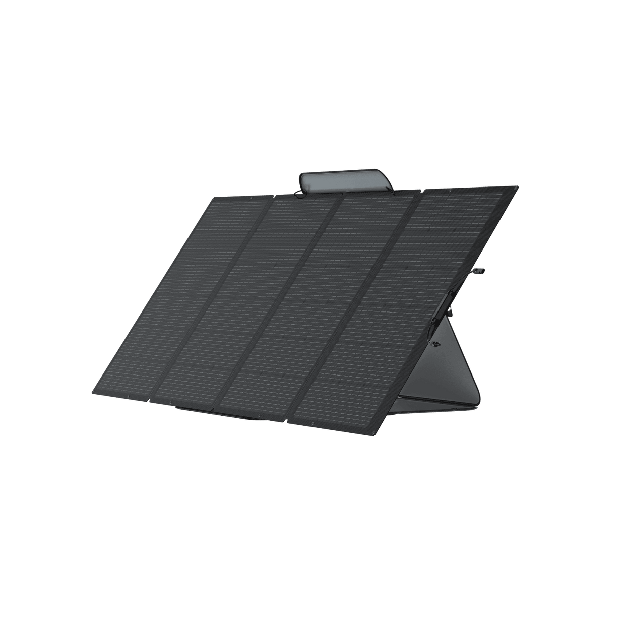
EcoFlow 400W Rigid Solar Panel
Constructed with high-purity monocrystalline silicon cells boasting a 23% conversion efficiency rating. Features robust IP68 waterproof weatherproofing, pre-drilled mounting holes, and standardized MC4 connectors suitable for high-voltage string arrays.
- • Rated Power: 400W (STC)
- • Open Circuit Voltage (Voc): 37.1V
- • Short Circuit Current (Isc): 13.8A

Tier-1 Bifacial 400W+ Solar Panels
Dual-glass photovoltaic panels that capture direct sunlight on the front face while absorbing reflected albedo light from snow, light gravel, or concrete on the rear face—boosting real-world output by 15% to 25% over standard panels.
- • Rear-Side Gain: Up to +25% additional yield
- • Dual-Glass Fire Class A rating
- • Ideal for Ground Mount & Tracker systems
Step-by-Step Solar Panel Array Sizing Reference
Use this sizing reference matrix to match common off-grid battery capacities with required daily solar arrays across summer and winter conditions:
| Battery Bank Usable Capacity | Typical Daily Load | Summer Array (5.0 PSH) | Winter Array (2.5 PSH) | Recommended Array Layout |
|---|---|---|---|---|
| 1,024 Wh (12.8V 100Ah) | 800 Wh / day | 220 W | 440 W | 2x 200W panels in series |
| 2,048 Wh (Bluetti AC200L / Delta 2 Max) | 1,600 Wh / day | 440 W | 880 W | 2x 400W or 4x 200W (2S2P) |
| 5,120 Wh (48V 100Ah Server Rack) | 3,800 Wh / day | 1,050 W | 2,100 W | 6x 400W panels (3S2P) |
| 10,240 Wh (Dual 48V Racks / Off-Grid Cabin) | 7,500 Wh / day | 2,100 W | 4,200 W | 10x to 12x 400W panels (Ground Mount) |
| 15,360 Wh (Whole-Home Backup / Sol-Ark / EG4) | 12,000 Wh / day | 3,300 W | 6,600 W | 16x 400W panels (2 strings of 8S) |
Common Solar Array Sizing Pitfalls to Avoid
- Relying on “Hours of Daylight” Instead of Peak Sun Hours: A location may have 14 hours of sunlight in June, but only 5.5 of those hours provide the intensity required for near-rated solar charging. Always calculate using local PSH data.
- Ignoring Winter Temperature Voltage Spikes: Failing to adjust for sub-freezing ambient temperatures is the #1 cause of blown MPPT input capacitors. Always verify the threshold.
- Mixing Panels with Different Amperage Ratings in Series: Wiring a 400W panel (10A ) in series with a 100W panel (5A ) limits the entire string to 5A—wasting half the output of the 400W panel. All panels in a series string must share identical current ratings.
- Under-Sizing Cable Gauge for Long Runs: Running high-current, low-voltage solar arrays (such as 12V parallel arrays pulling 30A) through 10 AWG wire over 50 feet causes severe voltage drop exceeding 8%, dissipating valuable energy as heat before it reaches the battery.
Frequently Asked Questions
Can I connect more solar panel wattage than my charge controller is rated for?
Yes. Oversizing your solar array (called overpaneling) by 20% to 35% is standard practice. Modern MPPT charge controllers will automatically limit their incoming current to protect internal circuitry while allowing your system to reach peak charging output earlier in the morning and sustain it later in the afternoon. You must, however, strictly remain under the controller’s maximum input voltage ().
How many solar panels do I need to charge a 100Ah 12V lithium battery in one day?
A 12V 100Ah LiFePO4 battery holds approximately 1,280 Wh of energy. Assuming a 80% discharge (1,024 Wh deficit) and an average of 4 Peak Sun Hours with standard 0.75 derating, you need approximately 340W of solar panels. Two 200W panels or one 400W panel will comfortably recharge the battery from empty in a single sunny day.
Should I wire my solar panels in series or parallel?
If your solar panels have an unobstructed view of the sky and your charge controller has sufficient voltage headroom, series wiring is superior because higher voltage allows thinner wire gauges and reduces heat loss over long distances. If parts of your array experience partial shading throughout the day or your controller has a low voltage limit (such as 50V or 100V), a parallel or series-parallel (2S2P) configuration prevents shading on one panel from throttling the entire system.
Why are my 400W solar panels only generating 310W?
Solar panels are tested under laboratory Standard Test Conditions (STC) at () cell temperature. Under real-world midday sun, cell temperatures frequently reach to , causing thermal voltage drop. Factoring in dust, atmospheric haze, inverter conversion losses, and sun angle, panels typically deliver 75% to 85% of their rated STC wattage under clear skies.