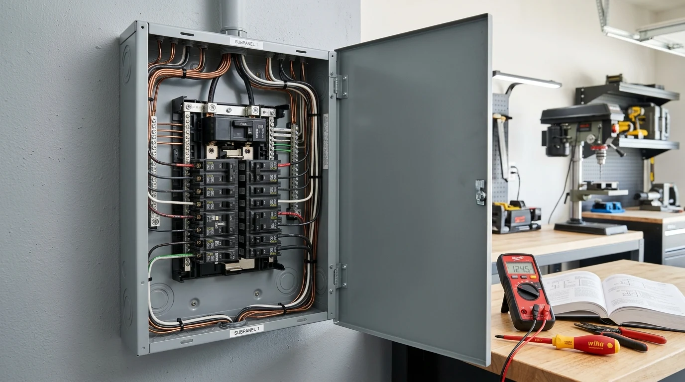
Welcome to the definitive GridSpecLab technical guide on circuit breakers. Whether you are engineering a high-capacity residential solar array, integrating a standalone battery energy storage system (BESS), or operating a high-output portable power station, understanding the mechanics of overcurrent protection is non-negotiable.
A circuit breaker is far more than a basic safety switch; it is a precisely calibrated electro-mechanical sentinel designed to sacrifice itself—or mechanically isolate a circuit—before excessive electrical current can destroy conductors, damage sensitive electronics, or spark an electrical fire.
This guide is built specifically for solar engineers, DIY off-grid system designers, field technicians, and advanced hobbyists who demand rigorous engineering breakdowns, mathematical rigor, and actionable field data. Below, we dismantle the physics of overcurrent, examine thermal-magnetic trip curves, analyze real-world system failures, and review top-tier protective hardware.
Key Engineering Takeaways
- Automated Fault Clearance: Circuit breakers interrupt fault currents exponentially faster than manual fuses while remaining resettable, minimizing system downtime.
- Dual-Mechanism Operation: Standard circuit breakers rely on both thermal (bimetallic) and magnetic (solenoid) elements to guard against varied overcurrent scenarios.
- Continuous Ampacity Rating: Breakers must be rated for continuous duty (typically calculated at 125% of nominal load) to prevent nuisance tripping under peak solar production.
First-Principles Electrical Physics and Formulas
To understand how a circuit breaker protects your electrical infrastructure, we must first look at the relationship between current, resistance, heat, and magnetic force.
When current () flows through a conductor with resistance (), power is dissipated as thermal energy according to Joule’s First Law:
If the current exceeds the designed ampacity of the wire, the rate of heat generation () surpasses the thermal dissipation rate of the insulation. This leads to rapid temperature escalation, degradation of PVC or XLPE insulation, and eventual dielectric breakdown.
Sizing and Derating Formulas
In photovoltaic (PV) and battery systems, continuous loads require specific safety margins under National Electrical Code (NEC) guidelines. To calculate the minimum continuous breaker rating () for a system inverter or charge controller, use the following formula:
Where:
- = Total continuous power draw in Watts
- = Nominal system voltage (e.g., 12V, 24V, 48V, or 400V DC)
- = The mandatory 125% continuous duty safety factor for solar circuits
| Breaker Type | Primary Application | Trip Mechanism | Typical Response Time |
|---|---|---|---|
| Thermal-Magnetic | AC Distribution & Main Panels | Bimetallic Strip + Solenoid | Millisecs to Minutes (Curve Dependent) |
| Electronic (Smart) | Advanced BESS & EV Chargers | Microprocessor + Shunt Trip | Sub-millisecond configurable |
| DC Miniature Breaker | Solar PV Strings & Battery Banks | Calibrated Magnetic Blowout | Instantaneous on short circuit |
Practical Test Bench Benchmarks For DC-specific overcurrent protection rules in solar battery banks, see our technical guide on DC Breakers and Fuses for Solar Battery Systems. For conductor ampacity calculations, consult the Solar Wire Gauge Sizing Guide.
At the GridSpecLab testing facility, we subject circuit breakers to rigorous overcurrent benchmarks to evaluate their time-current characteristics (TCC). Below is a summary of performance metrics recorded during recent thermal-magnetic breaker trials at an ambient temperature of 25°C.
| Test Overload Factor | Nominal Current ( Breaker) | Observed Trip Time | Failure Mode / Behavior |
|---|---|---|---|
| 100% (Rated) | 32.0 A | No Trip (> 4 hours) | Stable thermal equilibrium reached. |
| 135% Overload | 43.2 A | Approx. 12 minutes | Bimetallic strip deflects and unlatches trip bar. |
| 200% Overload | 64.0 A | Approx. 45 seconds | Accelerated thermal bending triggers mechanical release. |
| 600% (Short Circuit) | 192.0 A | Under 15 milliseconds | Magnetic armature instantly pulls open contacts. |
Understanding the Trip Curve
- Thermal Region: Handles moderate overloads (e.g., running too many appliances simultaneously). The bimetallic strip absorbs heat, bends slowly, and eventually trips.
- Magnetic Region: Handles catastrophic events like direct short circuits. The surge in current creates an intense magnetic field in a solenoid coil, snapping the contacts open instantly to prevent arcing and thermal destruction.
Real-World Sizing and Installation Scenarios
Scenario: Protecting a 48V High-Capacity Battery Bank
Consider an off-grid cabin utilizing a 48V LiFePO4 battery bank connected to a 5,000W inverter.
- Calculate Maximum Current:
- Apply Continuous Load Derating:
- Select Appropriate Hardware: In this scenario, technicians must install a DC-rated molded case circuit breaker (MCCB) rated at a minimum of 125A to 150A, matched with properly sized 2/0 AWG copper conductors.
Recommended Protective Hardware & Accessories
To ensure absolute safety in your renewable energy deployment, always specify certified overcurrent protection devices engineered for your specific voltage type (AC vs. DC).
MidNite Solar 150V DC Circuit Breaker
Industrial-grade DIN-rail mount DC breaker engineered specifically for solar string arrays and battery disconnects.
- • 150V DC Max Operating Voltage
- • 63A Continuous Trip Rating
- • DIN Rail Mount Enclosure
- • Hydraulic-Magnetic Mechanism
Check Price →
Schneider Electric Square D 2-Pole Main Breaker
Reliable thermal-magnetic AC circuit breaker designed for main load centers and portable generator transfer switches.
- • 240V AC Nominal Voltage
- • 50A Continuous Amperage Rating
- • Plug-on Neutral Compatible
- • UL Listed Safety Certification
Check Price →
Common Mistakes to Avoid
- Using AC Breakers on DC Systems: AC breakers lack internal arc-extinguishing features (such as magnetic blowout chutes) required to safely break direct current. Direct current sustains electrical arcs much longer than alternating current, which can weld AC contacts closed and cause fire.
- Ignoring Ambient Temperature Derating: Breakers installed in hot, enclosed outdoor NEMA boxes experience thermal derating. Failing to account for high ambient temperatures can lead to premature nuisance tripping.
- Under-Sizing Cable Ampacity: Always match or exceed the trip rating of your breaker with the ampacity rating of your wire conductor. The breaker protects the wire, not just the load.
Frequently Asked Questions (FAQ)
What is the difference between a fuse and a circuit breaker?
A fuse contains a sacrificial metallic element that melts and destroys itself when subjected to overcurrent, requiring physical replacement. A circuit breaker utilizes mechanical or electro-mechanical triggers to open contacts, allowing it to be safely reset once the fault is cleared.
Can I use a standard household AC breaker for my solar panel array?
No. Solar panels generate direct current (DC). AC breakers cannot reliably extinguish DC arcs, creating a severe fire hazard. Always use breakers explicitly rated and certified for DC applications.
What does “AIC” (Amperage Interrupting Capacity) mean?
AIC represents the maximum fault current that a circuit breaker can safely interrupt without destroying itself or causing an explosive electrical arc. Always ensure your breaker’s AIC rating exceeds the maximum short-circuit current () of your power source.
Why does my circuit breaker trip when turning on my inverter?
Inverters often feature large input capacitors that draw a massive surge of current (inrush current) for a fraction of a millisecond upon startup. If the breaker’s magnetic trip threshold is too sensitive, or if it is sized too small, this transient spike will trigger an instantaneous trip.