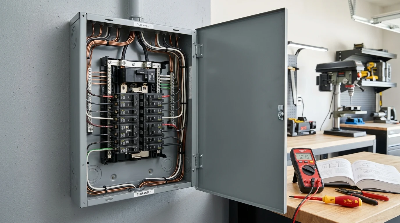
A single 48V 100Ah Lithium Iron Phosphate (LiFePO4) battery module stores roughly 5.12 kWh of electrochemical energy. Under normal conditions, its internal Battery Management System (BMS) manages discharge currents safely between 50A and 100A.
However, if an ungrounded battery positive cable rubs against a metal chassis or an inverter input capacitor suffers a catastrophic internal short circuit, that same battery pack can dump 10,000 to 20,000 Amperes of instantaneous fault current into the circuit in milliseconds.
If you rely on an automotive plastic blade fuse, an improper AC miniature circuit breaker (MCB), or an under-rated ANL fuse to clear that fault, the protective device will not trip safely. It will violently rupture, vaporize its contact terminals, and sustain an incandescent electrical plasma arc exceeding 5,000°F—igniting cables and battery enclosures.
Protecting a solar and battery storage system requires understanding DC arc suppression physics, selecting the correct Ampere Interrupting Capacity (AIC), and calculating conductor protection sizing under National Electrical Code (NEC) rules.
Fuses and circuit breakers are installed primarily to protect the copper conductor from catching fire, not the appliance at the end of the wire. Every OCPD rating must be equal to or greater than 125% of the continuous operating load, but strictly less than or equal to the maximum ampacity of the connected cable.
DC Arcing Physics vs. AC Zero-Crossing
The most dangerous mistake in DIY solar installations is using residential AC circuit breakers in a direct current (DC) battery or PV string circuit.
To understand why this is catastrophic, look at how Alternating Current (AC) behaves compared to Direct Current (DC):
- AC Waveforms Have Natural Zero-Crossings: In a 60Hz alternating current circuit (standard in North America), the voltage and current swing from positive to negative, crossing through 0 Volts exactly 120 times every second. When an AC circuit breaker mechanical contact snaps open, the electric arc naturally collapses and extinguishes the moment the sinusoidal waveform crosses zero.
- DC Current Has Zero Zero-Crossings: Direct current maintains continuous, unwavering polarity and voltage. When mechanical contacts open under a 48V or 100V DC load, the high electrical potential ionizes the surrounding air into a conductive plasma channel. The arc does not extinguish on its own; it continues burning across the contact gap until the breaker housing melts or the circuit vaporizes.
True DC-rated circuit breakers incorporate specialized arc chutes (de-ionizing metal plates) and permanent magnetic blowout coils. When contacts open, the magnetic field exerts a Lorentz force on the charged plasma, stretching the arc sideways into the splitter plates to rapidly cool and extinguish it. Using an AC breaker in a high-current DC circuit eliminates this mechanism, turning the breaker into an ignition source.
Prospective Short-Circuit Current & AIC Ratings
When choosing overcurrent protection for lithium battery banks, continuous amperage rating (e.g., 200A or 250A) is only the first specification to check. You must also verify the Ampere Interrupting Capacity (AIC), also labeled as Interrupting Rating (IR) or Breaking Capacity ().
The AIC rating is the maximum instantaneous short-circuit current that a fuse or breaker can safely interrupt at its rated voltage without rupturing, welding its contacts, or expelling flaming debris.
The Math: Estimating Lithium Fault Current ()
Modern prismatic LiFePO4 cells, such as those used in EG4 48V Server Rack Batteries or DIY 280Ah packs, feature exceptionally low internal resistance ( per cell):
For a 16-cell 48V 100Ah pack with total internal resistance (0.006 Ohms) plus 4 feet of 2/0 AWG copper cable ():
If two or three battery modules are wired in parallel on a common busbar, total internal resistance drops dramatically:
If you install a protective fuse with an AIC rating of only 2,000A on that busbar, the 20,000A fault current will blow right through the fuse body, establishing an unquenched arc across the melted terminals.
Fuse Types Compared: Class T vs. ANL vs. MRBF vs. Mega
Not all DC fuses are engineered for the extreme discharge capabilities of modern lithium batteries.
| Fuse Type | AIC Rating (Fault Current) | Max Voltage Rating | Clearing Speed | Recommended Application |
|---|---|---|---|---|
| Class T Fuse (JLLN / JJN) | 20,000A @ 125V DC (100,000A @ AC) | 125V – 160V DC | Extremely Fast (<2ms) | Mandatory for 48V LiFePO4 battery banks >200Ah |
| MRBF (Marine Rated Battery Fuse) | 10,000A @ 14V DC / 2,000A @ 58V DC | 58V DC | Fast-Acting | Terminal post mounting on 12V/24V van/boat batteries |
| ANL Fuse | 2,700A @ 32V / 6,000A @ 32V (ignition protected) | 32V – 80V DC | Time-Delay (Slow) | Lead-acid battery banks; small 12V inverters under 1500W |
| Mega Fuse / MIDI Fuse | 2,000A @ 32V DC | 32V – 58V DC | Time-Delay | Sub-circuit branch distribution; NEVER main lithium bank fuse |
Why Class T Is the Gold Standard for 48V Systems
Under NEC 705 and ABYC E-11 safety guidelines, a battery main overcurrent device must have an interrupting rating equal to or exceeding the battery’s maximum prospective short-circuit current.
A high-grade Class T fuse features a ceramic body filled with granular silica sand. When the internal silver element melts during a short circuit, the explosive energy fuses the sand into non-conductive glass (fulgurite), instantly extinguishing the arc in less than 2 milliseconds. No other fuse format delivers 20,000A AIC protection at 125V DC in such a compact, cost-effective form factor.
How to Size Fuses and Breakers: The NEC 125% Rule
Sizing overcurrent protection follows a strict sequence: determine continuous load current, apply safety multipliers, and confirm that the cable gauge selected safely carries that amperage.
Where is the lowest operating battery voltage before inverter shutdown, and is the full-load conversion efficiency (typically 0.88 to 0.90).
Worked Calculation: Sizing for a 5,000W 48V Inverter
Consider a 5,000W continuous pure sine wave inverter connected to a 48V LiFePO4 battery bank:
- Continuous Rated Output:
- Low-Voltage Inverter Disconnect: (2.75V per cell)
- Inverter Efficiency ():
Calculate maximum continuous DC operating current:
Apply NEC 125% continuous duty factor:
Next standard fuse size up: 175A or 200A Class T Fuse.
Now check the cable ampacity:
- 1/0 AWG copper cable ( rated) has an ampacity of 150A in conduit or 245A in free air.
- 2/0 AWG copper cable ( rated) has an ampacity of 175A in conduit or 300A in free air.
- Selection: Use 2/0 AWG copper cable paired with a 200A Class T fuse. The 200A fuse protects the 2/0 AWG wire while allowing full 5,000W continuous inverter operation without nuisance tripping.
Circuit Breakers vs. Fuses: Which Should You Install?
Both circuit breakers and fuses provide overcurrent protection, but they serve different operational roles in a solar power system:

Class T Fuse at Battery Terminal
Always place a Class T fuse within 7 inches of the battery bank’s ungrounded positive terminal. Because it contains no mechanical levers or springs that can jam or arc-weld shut, it provides an absolute failsafe barrier against catastrophic short-circuit currents.
- • Interrupting Capacity: 20,000A @ 125V DC
- • Trip Speed: Ultra-fast current limiting
- • Ideal Location: Positive battery busbar input

Polarized DC Circuit Breakers
Install DIN-rail or panel-mount DC circuit breakers between your solar panel strings and MPPT charge controller. They provide overcurrent protection and serve as a convenient physical disconnect switch for routine maintenance or rapid shutdown.
- • Dual Role: Overcurrent protection + isolation switch
- • Reusable: No replacement fuses required
- • Voltage Rating: Up to 500V DC per pole
Sizing Solar PV String Fuses & Breakers
While battery overcurrent devices protect against high-amperage short circuits from battery storage, solar PV string fuses protect against back-fed reverse currents from parallel strings.
Under NEC 690.8, PV string overcurrent protection is required whenever three or more solar strings are wired in parallel. If one string suffers an internal ground fault or shorted diode, the remaining parallel strings will dump all their current backward through that faulted string, melting the panel wiring.
Sizing Formula for PV String Fuses:
Where:
- is the module Short Circuit Current at STC.
- The first factor accounts for continuous operation.
- The second factor accounts for real-world solar irradiance exceeding 1,000 W/m² due to cloud-edge reflection (albedo effect).
For example, a solar panel with an of 12.5A:
Always verify that your calculated fuse rating does not exceed the Maximum Series Fuse Rating printed on the solar panel’s manufacturer specification label.
Crucial Physical Installation Rules
- Keep the Distance Under 7 Inches: Per NEC and ABYC guidelines, the main battery fuse must be located within 7 inches (18 cm) of the ungrounded battery terminal post. If the cable between the battery post and fuse has protective non-conductive sheathing, this distance can extend to a maximum of 18 inches. Any unprotected conductor length before the fuse is an unmitigated fire risk.
- Beware of Breaker Polarity Markings: Many high-voltage DC breakers have dedicated
+and-terminal labels. These utilize internal permanent magnets to direct electrical arcs into the arc chute. Wiring a polarized DC breaker backward reverses the magnetic force, pulling the arc away from the chute and locking it inside the casing. For bidirectional battery charging/discharging lines, use only non-polarized DC circuit breakers. - Torque All Fasteners to Spec: Loose fuse block nuts and loose breaker terminal screws create high electrical resistance points. At 150A of current, a tiny loose contact generates of pure localized thermal heat—melting fuse blocks and triggering nuisance trips.
Frequently Asked Questions
Why can’t I use a regular AC house breaker for my 48V solar battery?
AC circuit breakers rely on the natural zero-crossing of alternating current (where voltage drops to zero 120 times per second) to extinguish electrical arcs when tripped. DC power has no zero-crossing; the current flows continuously. An opening AC breaker contact in a DC circuit creates a persistent plasma arc that melts the contacts and ignites the breaker housing. Always use dedicated DC-rated circuit breakers.
What is the difference between an ANL fuse and a Class T fuse?
While both are bolt-down fuses, an ANL fuse has an Ampere Interrupting Capacity (AIC) of only 2,700A to 6,000A and trips with a slight time delay. A Class T fuse has an AIC rating of 20,000A to 100,000A and clears within 2 milliseconds. Because lithium LiFePO4 batteries can release more than 10,000A during a dead short, ANL fuses can rupture and arc over, whereas Class T fuses safely extinguish the fault.
Where should the main battery fuse be installed?
The main overcurrent protection fuse must be installed on the ungrounded positive battery cable within 7 inches of the battery terminal post (or within 18 inches if enclosed in a protective conduit). Placing the fuse further away leaves the intermediate cable unprotected if it shorts against the equipment chassis or frame.
Do I need a fuse on my solar panel string if I only have one or two strings?
If you only have one or two strings connected to an MPPT charge controller, string fuses are generally not required by NEC 690.9 because one string cannot produce enough reverse current to overload the other string’s conductors. However, once you connect three or more strings in parallel, branch combiner fuses or circuit breakers on each string are mandatory.