In solar power engineering, wires are not passive conduits—they are physical resistors. Every foot of copper wire offers resistance to flowing electrical current, transforming precious harvested solar energy into wasted heat ( power loss).
While alternating current (AC) at 120V or 240V tolerates longer distances with modest wire gauges, low-voltage direct current (DC) from solar panel strings and 12V/24V/48V battery banks is extraordinarily vulnerable to voltage drop.
Select a wire that is just two gauges too thin for your battery-to-inverter run, and your inverter will trip on low-voltage cut-off while your battery is still half full. Under-size your solar PV string cables, and you will lose hundreds of kilowatt-hours every year to thermal dissipation.
Below, we provide the exact engineering formulas, NEC ampacity tables, and practical sizing rules to select the correct American Wire Gauge (AWG) for every cable in your solar setup.
Always size conductors to satisfy two distinct criteria: 1) Thermal Ampacity Safety (the wire must safely carry the circuit’s maximum continuous current without exceeding insulation temperature limits) and 2) Voltage Drop Efficiency (total voltage drop must remain below 3% for solar PV strings and below 1.5%–2% for battery-to-inverter cables). Whichever requirement demands the thicker gauge governs the installation.
The Physics of Voltage Drop: Formulas & Calculations
Voltage drop occurs when electrical resistance in the copper conductor opposes current flow. The voltage drop formula for single-phase direct-current (DC) circuits is:
Where:
- = Voltage lost across the wire (in Volts).
- = Total round-trip circuit length in feet (the distance from the power source to the load and back along the negative return).
- = Maximum circuit current in Amperes.
- = Conductor resistance in Ohms per 1,000 feet (determined by AWG size).
To calculate percentage voltage drop:
Why System Voltage Changes Everything
Notice that system voltage () is in the denominator. This is why low-voltage systems suffer catastrophic losses:
If you drop across a cable run:
- In a 12V system, (Severe! Inverter low-voltage cutoff will trip).
- In a 48V system, .
- In a 200V high-voltage solar string, (Imperceptible).
This fundamental physical law explains why modern off-grid setups wire solar panels in high-voltage series strings. To understand series vs. parallel wiring dynamics, see our guide on Series vs. Parallel Solar Wiring for Power Stations.
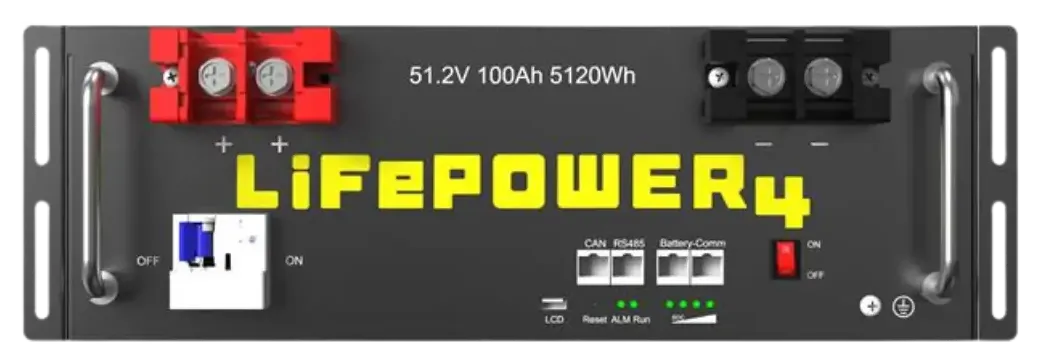
Figure 1: High-capacity battery connections require heavy 2/0 or 4/0 AWG fine-stranded pure copper cables to eliminate voltage drop and prevent thermal heating under high continuous inverter loads.
AWG Copper Conductor Resistance & Ampacity Reference
Below is the standard engineering reference for pure annealed copper wire (NEC Table 310.16, 75°C/90°C insulation rating):
| Wire Size (AWG) | Resistance (Ω per 1,000 ft) | Max Continuous Ampacity (90°C) | Max Recommended Fuse | Typical Solar Application |
|---|---|---|---|---|
| 12 AWG | 1.93 Ω | 25 A | 20 A | Low-power portable panels, 12V lighting circuits |
| 10 AWG | 1.21 Ω | 35 A | 30 A | Standard rooftop PV string cables (MC4 connectors) |
| 8 AWG | 0.764 Ω | 50 A | 40 A | Long PV string runs, small 24V/48V charge controllers |
| 6 AWG | 0.491 Ω | 65 A | 60 A | 60A–80A MPPT controller to battery bank interconnects |
| 4 AWG | 0.308 Ω | 85 A | 80 A | 48V inverters up to 3,000W continuous |
| 2 AWG | 0.194 Ω | 115 A | 100 A | 24V inverters (2,000W) or 48V systems (5,000W) |
| 1/0 AWG | 0.122 Ω | 150 A | 150 A | Heavy 48V battery busbar feeds, 6kW inverters |
| 2/0 AWG | 0.096 Ω | 175 A | 200 A | Server rack battery interconnects (100A–200A) |
| 4/0 AWG | 0.060 Ω | 230 A | 250 A – 300 A | High-power 12kW split-phase hybrid inverters |
Sizing Solar Panel Array Strings: Distance vs. Gauge
Standard solar PV wire (USE-2 or PV Wire rated for 600V/1000V UV exposure) is typically terminated with 10 AWG copper.
How far can you run 10 AWG wire before exceeding the critical 3% voltage drop limit?
-
Case 1: Low-Voltage Parallel Setup (): At just 25 feet away, 10 AWG wire hits maximum allowable voltage drop!
-
Case 2: High-Voltage Series String ():
By wiring panels in high-voltage series, you can place your ground mount solar array ten times further away (250 feet) using the exact same standard 10 AWG wire! To explore ground mount racking options that support remote placement, review our Best Solar Panel Ground Mounts Guide.
Battery-to-Inverter Cables: Why Fine-Stranded Copper is Mandatory
Connecting a battery bank to an inverter involves massive DC currents. When an inverter supplies 5,000 continuous watts from a 48V nominal battery bank:
During instantaneous motor surges, current can double to 230 Amps!
Critical Rules for Battery Cables:
- Never Use Stiff Romex or Building Wire: Battery connections experience continuous mechanical micro-vibrations from inverter cooling fans and thermal cycling. Always use Class K or Class M fine-stranded copper welding cable (e.g., UL 1426 Marine or SAE J1127). Fine stranding offers superior flexibility, reduces internal contact resistance, and prevents terminal fatigue.
- Identical Cable Lengths for Parallel Batteries: When linking multiple battery packs in parallel to a common busbar, every positive and negative cable must be the exact same length and gauge down to the quarter inch. If one cable is 6 inches shorter than another, its lower resistance will cause that battery module to deliver disproportionately more current, inducing severe cell imbalance. Read our technical guide on BMS Cell Balancing & Failure Modes.
Overcurrent Protection: Sizing Fuses and Circuit Breakers
A fundamental tenet of electrical safety: Fuses and circuit breakers are installed to protect the wire from melting and catching fire, not to protect the appliance.
The NEC 125% Rule
Under NEC Article 690.8, continuous solar currents must be multiplied by a safety factor of before selecting fuse ratings:
For example, if your charge controller delivers a continuous charging current of to your battery bank:
You would install an 80A fuse on a conductor rated for at least 80A of ampacity (4 AWG copper).
Fuse Type Selection: Class-T vs. ANL
- Class-T Fuses (Mandatory for Lithium): Lithium battery banks have extremely low internal resistance and can deliver catastrophic fault currents exceeding 10,000 to 20,000 Amps. Standard automotive fuses (MIDI, Mega, ANL) can physically arc over and explode under lithium short circuits. Always specify Class-T fuses (rated for 20,000A interrupt capacity / AIC) directly on the main battery positive terminal.
- Thermal DC Circuit Breakers: Ideal between solar panel strings and charge controllers, providing both overcurrent protection and an accessible manual disconnect switch for servicing.
Frequently Asked Questions (FAQ)
Can I use aluminum wire instead of copper for solar installations?
While large utility-scale solar farms use aluminum conductors for long underground feeder runs to save weight, copper is strongly recommended for residential and off-grid solar. Copper has 60% higher electrical conductivity, higher tensile strength, and far lower susceptibility to galvanic corrosion and thermal expansion loose connections. If aluminum is used, you must upsize the conductor by two full AWG gauges and use anti-oxidant joint compound.
What is the maximum acceptable voltage drop for a solar power system?
According to National Electrical Code (NEC) guidelines, total combined voltage drop from the solar array to the battery and onward to the inverter should not exceed 3%. For critical battery-to-inverter cables carrying hundreds of amps, aim for under 1.5% to 2% to prevent false inverter low-voltage alarms.
Does wire insulation temperature rating affect ampacity?
Yes. Wire ampacity depends heavily on its insulation rating. Most modern solar PV and marine battery cables use 90°C or 105°C insulation (such as XLPE or EPDM), which permits significantly higher continuous current than older 60°C or 75°C building wire (TW/THW). Always match your ampacity calculations to your specific conductor’s temperature rating.