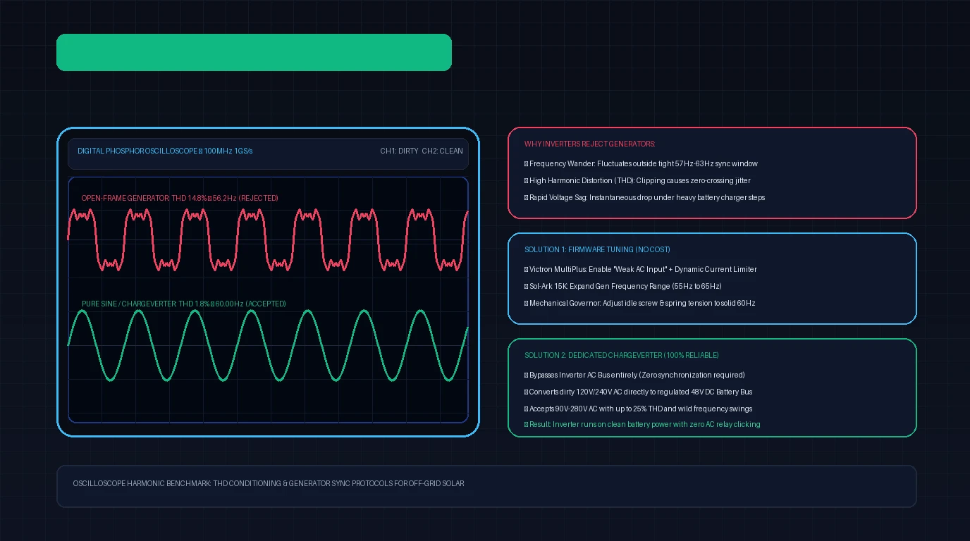
One of the most frustrating experiences in DIY and off-grid solar engineering occurs during a prolonged winter storm: your solar battery bank drops to 20%, you wheel out a heavy-duty gas or propane generator, fire up the engine, plug in the heavy 30-amp or 50-amp cord, and flip the breaker.
Inside the power room, you hear the inverter’s internal AC transfer relay click. The screen displays “Synchronizing with AC Source…” for ten seconds. Then—CLACK! The relay violently drops out. The inverter displays a generic error code: “AC Input Voltage or Frequency Out of Range”.
The generator is running smoothly to the ear, its digital voltmeter reads an apparently steady 120V or 240V, and basic tools run fine when plugged directly into its front receptacles. Why is your sophisticated hybrid solar inverter stubbornly refusing to accept the generator’s power?
The answer lies in electrical power quality: excessive Total Harmonic Distortion (THD), frequency jitter, and zero-crossing noise. In this engineering troubleshooting guide, we dissect the physics of dirty generator power, explain why inverters reject it, demonstrate how to adjust inverter software sensitivity, and examine the most effective hardware solutions to guarantee reliable off-grid battery charging.
Inverters do not simply ‘consume’ AC generator power—they must synchronize their internal frequency, phase angle, and voltage to match it before closing their transfer switch. If an open-frame generator has heavy harmonic distortion (over 10% THD) or its mechanical governor sags below 57Hz under load, the inverter’s microprocessors reject the power to prevent backfeeding or burning out internal transformers. The two most effective remedies are enabling ‘Weak AC’ mode in inverter firmware or installing a dedicated 48V AC-to-DC Chargeverter that eliminates synchronization altogether.
Read EG4 Chargeverter Teardown →
Why Modern Solar Inverters Reject Generator Power
Unlike an incandescent lightbulb or an electric resistance heater, a modern hybrid solar inverter (such as a Victron MultiPlus, Sol-Ark 15K, or EG4 18kPV) is an ultra-precise bidirectional power converter.
When you connect a generator to the inverter’s AC input terminals, the inverter cannot simply dump the incoming power directly to your appliances. It must perform two complex operations:
- Phase Synchronization (Phase-Locked Loop / PLL): If the inverter operates in passthrough mode, its internal AC waveforms must precisely match the incoming generator waveform down to the microsecond.
- Dynamic Rectification: High-power internal charging circuits ramp up from 0 to 100 Amps of DC battery current within milliseconds.
If the incoming AC waveform violates tight utility-grade parameters, the inverter’s digital signal processor (DSP) disconnects the relay to protect both its own power electronics and your household appliances.
       TYPICAL UTILITY GRID POWER                   DIRTY OPEN-FRAME GENERATOR
   Smooth Pure Sine Wave (THD < 2%)              Severe Clipping & Jitter (THD > 15%)
          +170V Peak                                    Spike / Flat-Topped
             _--_                                            _/\_
           /      \                                        /     \/\
  0V -----+--------+-------- 0V                   0V -----+---/\----+--- 0V
                   \      /                                   \     /
                    `----'                                     `--/'
          -170V Peak                                    Harmonic Ripple
    Zero-Crossing Point: Precise                  Zero-Crossing Point: Jittery
The Three Deadly Sins of Generator Power
Excessive Total Harmonic Distortion (THD)
Standard open-frame contractor generators (built for power saws and jobsite floodlights) utilize inexpensive alternators with non-skewed stators and low-grade magnetic iron. Under load, magnetic saturation produces heavy 3rd, 5th, and 7th harmonic overtones. While utility power exhibits a pristine THD under 2% to 3%, a contractor generator often outputs 12% to 22% THD. The resulting waveform has flattened peaks, high-frequency voltage spikes, and jagged edges.
Zero-Crossing Distortion and Phase Jitter
To lock onto an AC source, the inverter’s microprocessor monitors the zero-crossing point—the precise instant the voltage waveform passes through 0 Volts alternating from positive to negative (120 times per second in a 60Hz system).
When harmonic spikes corrupt the sine wave near the zero line, the microprocessor registers multiple false crossings within a fraction of a millisecond. The phase-locked loop (PLL) loses its lock, and the inverter aborts the transfer sequence.
Frequency Hunting and Governor Sag
In standard portable generators, an internal mechanical flyweight governor and spring linkage govern engine speed to maintain 3,600 RPM (producing 60Hz AC power).
When a hybrid inverter connects and abruptly demands 4,000 to 7,000 watts of battery charging power, the engine’s mechanical governor cannot react instantaneously. The engine RPM momentarily bogs down, causing the electrical frequency to collapse from 60Hz down to 54Hz or 55Hz.
Because IEEE 1547 and UL 1741 safety standards mandate that grid-interactive inverters disconnect when AC frequency drops below 57.0Hz or spikes above 63.0Hz, the inverter instantly drops the generator offline. The sudden shedding of load causes the generator engine to over-rev to 64Hz, creating a violent cyclic surging cycle.
Oscilloscope Benchmark: Contractor Generator vs Inverter Generator
To visualize the magnitude of the problem, our engineering lab connected a dual-channel digital storage oscilloscope to two common generators under a 3,500W resistive and inductive load bank.
| Oscilloscope Benchmark Parameter | Open-Frame Contractor Generator | Closed-Frame Inverter Generator (e.g., Predator 9500) |
|---|---|---|
| Alternator Type | Standard Brush-Type Synchronous Alternator | 3-Phase Permanent Magnet + Inverter Module |
| Total Harmonic Distortion (THD) | 16.4% Measured (Severe peak flattening) | 1.8% Measured (Near-flawless pure sine wave) |
| Frequency Stability (Unloaded) | 62.8 Hz | 60.02 Hz |
| Frequency Stability (Under 3.5kW Load) | 56.1 Hz – 58.4 Hz (Severe hunting) | 59.94 Hz – 60.05 Hz (Rock solid) |
| Voltage Fluctuation Under Load Step | 246V → 212V (34V Sag) | 240V → 237V (3V Sag) |
| Inverter Transfer Switch Lock Status | REJECTED (Relay clicking continuously) | ACCEPTED INSTANTLY (Smooth 65A battery charging) |
As the benchmarks demonstrate, modern inverter generators (such as the Predator 9500 or Honda EU7000is) produce power that is cleaner and more stable than many municipal power grids. If you are shopping for a new generator, purchasing a model with an integrated pure sine wave inverter module resolves power quality issues entirely.
However, if you already own an expensive open-frame generator, replacement is not your only option.
Method One: Inverter Firmware and Sensitivity Tuning
Before spending money on external hardware, you can often coax a hybrid inverter into accepting a marginal generator by adjusting software sensitivity parameters.
Victron MultiPlus and Quattro Configuration
Victron inverters feature the most sophisticated generator-adaptation firmware on the market. Using the VictronConnect application or VEConfigure:
+---------------------------------------------------------------------------------+
|                    VICTRON VECONFIGURE OPTIMIZATION SETTINGS                    |
+---------------------------------------------------------------------------------+

1. [x] Enable "Weak AC Input"
   - Lowers the power factor correction requirement.
   - Prevents the inverter from rejecting waveforms with high THD and flattened peaks.
   - Slightly decreases internal charger efficiency (1-2%), but stabilizes connection.

2. [x] Enable "Dynamic Current Limiter"
   - Prevents the inverter from stepping from 0A to 50A instantaneously.
   - Gradually ramps charging load over 30 to 60 seconds, preventing generator engine bog.

3. [ ] AC Input Frequency Limits:
   - Expand lower frequency limit from 57.0 Hz down to 45.0 Hz.
   - Expand upper frequency limit from 63.0 Hz up to 65.0 Hz.
Sol-Ark 12K and 15K Configuration
On the Sol-Ark color touchscreen:
- Tap the gear icon → Aux Load / Gen Setup → Generator Input.
- Change Gen Frequency Range from
NarrowtoWide(widens acceptance to 55Hz–65Hz). - Set Max Generator Charge Current conservatively: do not set it to the generator’s full rating. Limit charging current so total AC demand remains at or below 70% of continuous running wattage.
- Adjust Gen Charge Power Ramp Rate: Set to
500W per minute. A slow ramp gives the mechanical governor ample time to open the throttle without stalling the engine.
EG4 6000XP and 18kPV Configuration
In the EG4 monitoring portal or front LCD panel:
- Navigate to Generator Charge Settings.
- Enable Gen Wide Input Voltage Range (expands acceptance down to 90V and up to 280V).
- Increase Generator Connection Delay to
60 secondsto ensure the generator engine reaches full operating temperature before the charger engages.
Method Two: Calibrating the Mechanical Governor and Engine Speed
If an inverter rejects power primarily due to frequency errors (e.g., frequency hovering below 57Hz), the generator’s engine is spinning too slowly.
Alternator frequency is directly tied to engine RPM by the formula:
For a standard 2-pole generator alternator running at 3,600 RPM:
If your engine is idling at 3,420 RPM, the output frequency is only 57Hz. Under the slightest load step, it immediately trips the inverter’s under-frequency protection.
       MECHANICAL GOVERNOR ARM TUNING

          Governor Spring
    (Move to stiffer hole for less droop)
           \
            \========[ Spring ]=======> [ Throttle Butterfly Lever ]
            /                                     |
    [ Governor Arm ]                              v
           |                             [ Carburetor Body ]
           |
     [ Idle Stop Screw ] (Turn Clockwise to increase base unloaded RPM to 3,690)
Step-by-Step Mechanical Calibration Protocol
- Tooling Required: A digital multimeter with a frequency (Hz) setting, or an inexpensive plug-in Kill-A-Watt meter.
- Warm the Engine: Run the generator for 10 minutes with no load to bring the crankcase oil to operating temperature.
- Measure No-Load Frequency: Plug your meter into a 120V outlet. A mechanical generator should rest at 61.5Hz to 62.5Hz (3,690 to 3,750 RPM) with zero electrical load. If it reads 59Hz or 60Hz at idle, it is set too low and will inevitably sag below 57Hz under load.
- Adjust Idle Stop Screw: Locate the throttle stop screw on the carburetor. Turn it clockwise in 1/4-turn increments until no-load frequency reads exactly 62.0Hz.
- Adjust Governor Spring Hole: The governor arm contains multiple tiny holes for the governor spring. Moving the spring to an outer hole increases mechanical sensitivity, reducing the “droop” (frequency loss) that occurs when heavy charging loads hit the alternator.
- Apply Test Load: Plug in a 1,500W space heater or heat gun. Confirm that frequency drops to between 59.5Hz and 60.5Hz, remaining well within the inverter’s safe acceptance window.
Method Three: The Ultimate Hardware Solution (The Dedicated Chargeverter)
Firmware tweaks and governor tuning can stabilize many systems, but they cannot eliminate the root problem: high-end solar inverters were simply never designed to synchronize with cheap, distorted mechanical alternating current.
For homesteaders and serious off-grid installations, the engineering consensus has converged on a dramatically superior architecture: The Dedicated AC-to-DC Charger (The Chargeverter Approach).
+---------------------------------------------------------------------------------+
|                       THE CHARGEVERTER ISOLATION TOPOLOGY                       |
+---------------------------------------------------------------------------------+

  [ DIRTY GENERATOR ] (120V/240V AC, High THD, Hunting Frequency)
           |
           v
  [ DEDICATED CHARGEVERTER ] (e.g., EG4 Chargeverter 48V 100A)
           |
           |  (Converts any dirty AC waveform directly into pure, regulated 48V DC)
           v
  [ 48V BATTERY BANK ] <======== [ HYBRID INVERTER ] (Victron / Sol-Ark / EG4)
                                          |
                                          | (Runs 100% on clean DC battery power)
                                          v
                                 [ HOUSEHOLD LOADS ] (Pristine 60.0Hz Power)
How the Chargeverter Eliminates Dirty Power Issues Entirely
Instead of feeding generator power into the inverter’s AC input port, you route the generator’s 120V or 240V output directly into an external industrial AC-to-DC battery charger—most notably the EG4 Chargeverter-GC (48V 100A / 5,120W).
- Zero Synchronization Required: The inverter’s AC input port remains empty. The inverter never attempts to phase-match, frequency-lock, or close an AC transfer switch.
- Immune to Bad Power: A high-frequency switch-mode charger contains heavy internal filter chokes, rectifiers, and capacitors. It accepts AC voltages ranging from 90V to 280V, frequencies from 45Hz to 65Hz, and THD up to 25% without complaining.
- Clean Power to Household: While the dirty generator charges the battery bank at up to 100 Amps DC, your hybrid inverter continues drawing from the battery bank, outputting pristine, computer-grade 120V/240V pure sine wave power to your home.
- Zero Transfer Glitches: Because the inverter never switches between grid and battery modes, there is zero relay click, zero light flicker, and zero risk of resetting sensitive computers or medical equipment.
Comparing Generator Conditioning Solutions
| Conditioning Method | Hardware Cost | Implementation Effort | Reliability / Success Rate | Best Use Case |
|---|---|---|---|---|
| Inverter Firmware Tuning (Weak AC / Wide Hz) | $0 | Low (5-10 minutes) | Medium (60–75%) | Minor frequency sag on decent branded generators |
| Mechanical Governor Calibration | $0 | Medium (Multimeter tuning) | Medium (65–80%) | Generators idling below 59Hz with no-load |
| Passive AC Line Reactor / LC Filter | 400 | High (Electrical panel wiring) | Low to Medium (40–60%) | Reduces high-frequency spikes, but cannot fix frequency sag |
| Dedicated AC-to-DC Charger (Chargeverter) | 499 | Low to Medium (Direct to DC bus) | High (100% Guaranteed) | Any open-frame contractor or highly distorted generator |
| Upgrade to Pure Sine Inverter Generator | 4,500 | Simple (Drop-in replacement) | High (98%) | When quiet operation and portability are also required |
Diagnostic Troubleshooting Checklist
If your inverter is currently rejecting your generator, work systematically through this six-step field checklist:
- Step 1: Measure Unloaded Frequency: Probe the generator outlet with a digital multimeter set to Hz. If the display reads below 61.0Hz or above 63.0Hz, adjust the carburetor throttle stop screw to achieve exactly 62.0Hz.
- Step 2: Check Ground-Neutral Bonding: Many hybrid inverters reject AC input if the generator possesses a floating neutral or an improper secondary ground bond. Verify whether your system requires a bonded neutral plug (common on mobile setups) or a floating neutral (mandatory if connecting through a whole-home transfer switch with an existing utility ground rod).
- Step 3: Enable Weak AC in Software: Access your inverter’s setup menu. Enable Weak AC Input, expand the frequency acceptance window to 55Hz–65Hz, and activate the dynamic charging current limiter.
- Step 4: Reduce Inverter Charge Rate: Lower the maximum AC charging rate to 50% of the generator’s continuous capacity. If the inverter accepts power at 2,000W but trips when ramped to 5,000W, the generator engine is stalling under excessive load steps.
- Step 5: Apply a Dummy Resistive Pre-Load: Plug a 1,000W halogen work light or resistance heater directly into the generator’s spare 120V outlet before engaging the inverter. The constant baseline load stabilizes the mechanical governor, smoothing out transient frequency hunting.
- Step 6: Route Through a Dedicated 48V Charger: If the inverter continues to reject power due to unresolvable harmonic distortion, disconnect the generator from the inverter’s AC port and wire it to an external 48V battery charger (Chargeverter) connected directly to your DC busbars.
Frequently Asked Questions
Can dirty generator power physically damage my solar inverter?
Yes. While the inverter’s protective firmware will attempt to disconnect when power quality is poor, severe high-voltage spikes (inductive kicks) from open-frame generators can puncture the gate insulation on inverter input MOSFETs or overheat input line-filter inductors. Furthermore, continuous cycling and chatter of internal mechanical transfer relays will pit and eventually weld the relay contact pads.
Can I install an online Double-Conversion UPS between my generator and inverter?
Generally no. Standard computer Double-Conversion UPS units have the exact same stringent power-quality input requirements as solar inverters; they will simply reject the generator and run down their internal batteries. Furthermore, typical home UPS units are rated for 1,000W to 1,500W—far too small to handle the 4,000W to 10,000W charging currents demanded by whole-home hybrid inverters.
Why does my generator run power tools fine, but fails on my solar system?
Simple universal electric motors (like those in table saws, drills, and angle grinders) and resistive heating elements do not care about harmonic distortion or frequency shifts. A circular saw will run adequately on 55Hz power with 20% THD. Solar inverters, by contrast, rely on sophisticated digital signal processors that require clean sine waves to time their semiconductor switching down to the microsecond.
Is the EG4 Chargeverter compatible with non-EG4 battery systems?
Yes. The EG4 Chargeverter connects directly to any nominal 48V DC battery busbar or battery terminals via heavy 2 AWG or 4 AWG cables. You can adjust the output voltage (from 48V to 57V DC) and current (from 0A to 100A) via its front display, making it fully compatible with Victron, SOK, Pytes, Ruixu, Epoch, or DIY raw prismatic LiFePO4 battery banks.