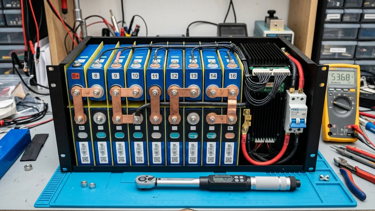
The 48-volt 100Ah server rack battery has established itself as the gold standard building block for modern residential off-grid systems and hybrid solar storage. Delivering 5.12 kilowatt-hours (kWh) of usable nominal energy at a safe, touchable potential (51.2V nominal), it pairs natively with high-power 120V/240V split-phase inverters like the Victron MultiPlus-II and EG4 18kPV.
However, buying pre-assembled, brand-name server rack batteries from commercial suppliers typically costs between 1,800 per unit (350 per kWh).
By assembling your own server rack battery using 16 raw Grade-A 3.2V prismatic LiFePO4 cells (such as EVE, CATL, or REPT) and a modular steel server-rack enclosure kit with a Smart BMS, you can assemble a state-of-the-art battery bank for under 750 total—slashing your storage investment down to roughly $135 per kWh.
Beyond the massive cost savings, building your own pack grants total hardware transparency: you control cell compression, choose premium active-balancing BMS electronics, and possess the mechanical knowledge to replace a single degraded cell a decade from now without discarding an entire multi-thousand-dollar battery.
In this definitive engineering walkthrough, we provide a complete bill of materials, detail cell layout and busbar torquing physics, explain foolproof BMS harness wiring, and outline the strict pre-commissioning safety checklist.
Building a 48V 16S battery requires 16 matched 3.2V 100Ah prismatic cells, an open-source or commercial server-rack case (e.g. Seplos Mason or Andy Off-Grid kit), a 100A–200A Smart BMS with closed-loop CAN/RS485 comms, and an integrated 125A–200A DC breaker. Always insulate between cell aluminum cases with 0.5mm FR4 epoxy sheets, torque busbars with a calibrated torque wrench to 5.0 Nm, and top-balance cells before final assembly.
Read Top Balancing Guide →
Bill of Materials and Cost Breakdown vs. Pre-Built Batteries
Before ordering components, let’s examine the raw economic reality. How does an engineered DIY server rack pack compare financially to commercial pre-built alternatives?
| Component / Feature | DIY 48V 100Ah (16S Build) | Commercial Pre-Built Pack | Savings / Benefit |
|---|---|---|---|
| 16x Grade-A Prismatic Cells | 440 (EVE / REPT 100Ah) | Proprietary / Unknown Grade | Verified factory QR test reports |
| Server Rack Case & Busbars | 220 (Steel Kit with Shunt) | Included in MSRP | Custom replaceable parts |
| Smart BMS (CAN / RS485) | 130 (JK / Seplos / Daly) | Locked proprietary BMS | Full Bluetooth app control |
| DC Breaker & Hardware | 50 (125A 2-Pole MCCB) | Integrated Breaker | Serviceable toggle switch |
| Total System Cost | 840 Total | 1,800 Total | Save Over $800 Per Unit |
| Cost per Usable kWh | ~320 / kWh | 58% Cost Reduction |
Essential Tools and Consumables Required
Before touching a single cell, assemble these professional tools on a grounded anti-static workspace:
- Digital Torque Wrench (1 to 20 Nm range): Mandatory for precision busbar torquing. Never use a standard ratchet.
- True-RMS Digital Multimeter: For cell voltage verification and continuity checks.
- Calibrated Bench Power Supply (0–30V, 10–20A): Required for parallel top-balancing raw cells to 3.65V.
- FR4 Epoxy Fiberglass Sheets (0.5mm thickness): Cut to match cell dimensions for physical and electrical isolation.
- High-Temperature Kapton Tape (polyimide): For bundling cells and securing NTC temperature sensors.
- Insulated Hand Tools: 10mm insulated socket and drivers to eliminate accidental short-circuit arcs.
Cell Layout, Busbar Torquing, and Epoxy Insulation Sheets
A 48V nominal LiFePO4 battery consists of 16 individual cells connected in series (16S):
The Critical Need for FR4 Epoxy Insulation
Every prismatic cell is encased in an aluminum jacket wrapped in a thin blue PVC shrink-sleeve.
Many DIYers assume this blue film is adequate electrical insulation. It is not.
The thin PVC film easily abrades or punctures from mechanical vibration or manufacturing burrs. Because the aluminum casing of many prismatic cells is connected internally to the positive cathode terminal or holds a floating voltage, two bare aluminum cases touching will create a dead short circuit between cells, causing violent arcing and thermal runaway.
Place a 0.5mm yellow FR4 epoxy fiberglass sheet between every single adjacent cell, as well as between the outer cells and the steel chassis walls. FR4 possesses a dielectric breakdown rating exceeding 20,000 Volts per millimeter, completely preventing chassis shorts.
16S Series Physical Arrangement (2x8 Matrix)
Standard 19-inch 4U server rack cases arrange the 16 cells into two parallel rows of eight cells (2x8 matrix). To create a 16S series circuit, alternate the polarity of adjacent cells:
B- [Neg]
[Pos]
[Neg]
[Pos]
[Neg]
[Pos]
[Neg]
[Pos]
B+ [Pos]
[Neg]
[Pos]
[Neg]
[Pos]
[Neg]
[Pos]
[Neg]
Busbar Sizing and Precision Torquing
Connecting the cell terminals in series requires flexible laminated copper busbars with nickel or tin electroplating to prevent galvanic oxidation between copper and aluminum:
- Why Flexible Busbars Matter: Prismatic cells physically expand and contract slightly during charge and discharge cycles. Rigid copper bars transfer mechanical shear force into the delicate laser-welded M6 terminal studs, cracking the cell seal over time. Flexible laminated busbars flex harmlessly with thermal expansion.
- Torque Specifications:
- Clean all terminal pads with 99% isopropyl alcohol.
- Thread stainless steel M6 serrated flange nuts by hand to avoid cross-threading.
- Using a calibrated torque wrench, tighten every nut to to (40 to 48 in-lbs).
- Warning: Exceeding will strip the internal aluminum threads or twist the terminal pad off the internal cell jelly roll.
BMS Wiring: Balance Leads, Temperature Probes, and Main Lugs
The Battery Management System (BMS) is the electronic heart of the battery pack. Popular options include the JK Smart BMS (with active 2A balancer), Seplos Mason BMS (with CAN/RS485 LCD screen), or Daly Smart BMS.
Connecting Main B- and P- Heavy Gauge Cables
Connect the heavy black B- (Battery Negative) silicone leads from the BMS directly to the Negative terminal of Cell 1. All current exiting or entering the battery must pass through the BMS internal MOSFET array.
Connect the P- (Pack Negative) lead from the BMS to the input terminal of the battery current shunt (or directly to the front negative output terminal).
The positive high-current cable runs from the Positive terminal of Cell 16 through the DC Circuit Breaker / Fuse directly to the positive front terminal post.
The Balance Lead Wiring Protocol: Zero Mistakes Allowed
The BMS includes a multi-conductor ribbon harness with 17 thin balance wires (B0 through B16):
- B0 (Black): Connects to the Negative terminal of Cell 1 (Ground reference).
- B1: Connects to the Positive terminal of Cell 1 (which is bridged to Cell 2 Negative).
- B2: Connects to the Positive terminal of Cell 2.
- Continue sequentially: B3 through B15 connect to the positive terminals of Cells 3 through 15.
- B16 (Red): Connects to the Positive terminal of Cell 16 (Main Pack Positive).
NEVER plug the balance harness into the BMS circuit board immediately after crimping. Plugging in an incorrectly indexed harness will instantly vaporize the micro-resistors on the BMS circuit board.
Hold the disconnected white plastic connector in your hand. Place the black multimeter probe on Pin 0 (B0). Probe Pin 1 through Pin 16 with the red lead: you must observe a steady, incremental rise of approximately +3.3V per pin (Pin 1 = 3.3V, Pin 2 = 6.6V, Pin 3 = 9.9V … Pin 16 = ~53.0V). If any voltage reads zero, negative, or skips a step, correct the wiring before plugging in.
Temperature Sensor (NTC) Placement
Most Smart BMS units include 2 to 4 external negative temperature coefficient (NTC) thermistors. These sensors are vital for executing low-temperature charging protection:
- Sensor 1: Tape firmly between Cell 4 and Cell 5 in the center of the front pack row.
- Sensor 2: Tape between Cell 12 and Cell 13 in the center of the rear row (where internal thermal buildup is highest).
- Sensor 3 (if equipped): Affix directly to the BMS aluminum heatsink plate to monitor power MOSFET switching temperatures under full 100A discharge.
125A–200A DC Breaker and Smart Shunt Installation
A server rack battery must incorporate dedicated overcurrent protection and an accurate current-sensing shunt inside the front enclosure.
DC Molded Case Circuit Breaker (MCCB) Sizing
Never install residential AC breakers into a 48V DC battery system. AC breakers rely on zero-crossing AC waveforms to extinguish electrical arcs; under DC current, opening an AC breaker can sustain an uninterrupted plasma flame that destroys the enclosure.
100A Continuous Inverter Duty Install a 125A 2-Pole polarized DC MCCB rated for a minimum of 60V DC and 10kA interrupting capacity (AIC).
150A–200A Surge Duty Install a 200A DC Breaker with 2/0 AWG high-flex silicone battery interconnect wire.
Smart Shunt Wiring
To ensure 100% accurate State of Charge tracking, connect the pack negative through a precision current shunt:
- Wire the P- lead from the BMS to the
BATTERY -side of the shunt. - Wire the
LOAD / SYSTEM -side of the shunt to the front panel negative terminal post. - Connect the thin 22 AWG power wire from the shunt’s sense terminal to the battery positive post (protected by a 1A inline fuse).
- The shunt measures bidirectional milli-volt drops across its internal manganin resistive bridge, calculating true amp-hours (Ah) into and out of the cells without drifting.
Pre-Commissioning Safety Checklist and Initial Charge Testing
Before closing the steel top cover and connecting your battery to an inverter, complete this rigorous laboratory pre-commissioning checklist:
Cell Compression Check Verify that the mechanical compression end-plates and tension rods are torqued according to manufacturer specifications (typically 300 kgf or ~12 psi of uniform face pressure) with spring washers in place to allow thermal breathing.
Torque Wrench Verification Re-verify all 16 cell terminal nuts with your calibrated torque wrench set to 5.0 Nm. Mark each verified nut with a dab of red torque seal paint.
Chassis Isolation Resistance Test With the breaker open, test resistance with a multimeter between the Main Battery Positive and the metal chassis, then between Battery Negative and the chassis. Resistance must read Open Loop (∞ Ohms). Any continuity indicates a dangerous short through an uninsulated cell wall.
BMS App Bluetooth Commissioning Plug in the verified balance harness. Turn on the BMS power switch. Open the smartphone app (e.g. JK BMS or Seplos app). Confirm all 16 cell voltages appear with delta voltage under . Set total battery capacity to 100Ah, cell overvoltage cutoff to 3.65V, and low temperature charge cutoff to 0°C (32°F).
Initial Slow Absorption Test Connect a 48V bench charger or solar inverter programmed to a gentle 10A charge current (). Monitor the BMS app continuously as the pack approaches 56.8V. Verify that active balancers engage smoothly and that no runner cell triggers an overvoltage cutoff.
Frequently Asked Questions
Can I build a 48V battery using 280Ah or 314Ah cells in the same case?
Yes, but larger capacity cells (like EVE LF280K or MB31 314Ah) require a larger server rack enclosure (typically 5U to 7U height instead of standard 4U). A 16S 314Ah build creates a massive 16.0kWh battery pack weighing approximately 280 lbs, delivering commercial-grade energy density at unbeatable $/kWh rates.
Is top-balancing really necessary if my BMS has an active balancer?
Yes. An active balancer typically moves between 0.6A and 2.0A of current. If two cells arrive from the factory with a 20Ah difference in state-of-charge, it would take an active balancer over 30 hours of continuous high-voltage operation to balance them. Top-balancing all 16 cells in parallel to 3.65V before assembly guarantees instant, flawless operation on day one.
Do I need a pre-charge resistor when connecting my DIY battery to an inverter?
Yes. When connecting a 48V battery to an uncharged inverter, the massive internal capacitor bank acts as an instantaneous short circuit. Without a pre-charge resistor, the 1,000A inrush current can weld breaker contacts or trigger the BMS into short-circuit lockout mode.
Can I parallel my DIY battery with commercial batteries like EG4 LifePower4?
Yes, provided both packs share identical nominal voltage (16S 51.2V LiFePO4) and are paralleled to common busbars using identical length cables. If operating in closed-loop communication, ensure the DIY BMS supports the Pylontech or EG4 CAN protocol so both batteries communicate harmoniously with the inverter.