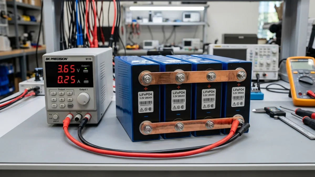
You have carefully assembled a 16S 48V DIY lithium battery pack using large-format EVE 280Ah or 314Ah prismatic cells. As your hybrid inverter or solar charge controller pumps 40 Amps into the pack, you open your smartphone BMS app.
Everything looks immaculate: all 16 cells are reading between 3.331V and 3.335V with a negligible 4-millivolt delta.
Then, as the total pack passes 54.0 Volts, chaos erupts. Within 90 seconds, Cell #4 skyrockets to 3.650V, triggering a high-voltage protection alarm and forcing the BMS to trip open its charging MOSFETs. Meanwhile, the remaining 15 cells are languishing at 3.340V to 3.360V—nowhere near fully charged!
This maddening phenomenon is known throughout the energy storage industry as a “High SoC Runner Cell.”
Why do cells appear perfectly balanced throughout the entire day, only to violently diverge in the final 5 minutes of charging? And why can standard passive BMS balancers never seem to fix it?
In this electrical engineering guide, we dissect the electrochemical knee curve of lithium iron phosphate, analyze why passive balancers fail under high charging currents, provide step-by-step benchtop procedures to bleed or boost individual runner cells, and explain the optimal charge controller voltage ceilings to permanently eliminate BMS disconnects.
LiFePO4 cell voltage is an illusion between 20% and 80% SoC; a 5mV delta in the flat middle tells you nothing about capacity. True cell imbalance only reveals itself above 3.45V per cell. Standard 50mA passive balancers cannot counteract 30A to 60A solar charging currents. To fix runner cells, install a 1A to 2A active inductive balancer, manually bleed the high runner cell with a 12V 55W automotive bulb dummy load, and lower your inverter bulk charge voltage from 57.6V to 55.2V (3.45V/cell).
Check Battery Bank Runtime & Capacity Calculator →
The Voltage Knee Curve: Why Imbalance Is Invisible in the Middle
Unlike lead-acid or NMC lithium-ion chemistries—where cell voltage rises linearly from empty to full—Lithium Iron Phosphate (LiFePO4) exhibits an ultra-flat open-circuit voltage profile:
Rapid voltage collapse. Voltage changes by over 600mV across the bottom 15% of capacity. A weak cell drops precipitously into the low-voltage cutoff floor.
Virtually flat voltage plateau. Two cells sitting at identical 3.325V can have a massive 30% difference in actual stored state-of-charge! Balancing here is completely useless.
The cathode is fully de-intercalated. Resistance spikes vertically. An extra 1Ah of current causes voltage to rocket from 3.42V to 3.65V in seconds.
Why the Runner Cell Shoots Up
Suppose Cell #4 was received from the factory at 60% SoC, while the other 15 cells were at 52% SoC (an 8% difference).
Because both states register exactly 3.33V on the flat plateau, your BMS reports near-perfect balance during the entire charging cycle.
However, once charging reaches the top of the curve, Cell #4 hits 100% capacity first. With no more vacant intercalation sites available in its graphite anode, its internal electrochemical resistance spikes. The incoming 40A charging current now drives a sharp voltage spike across Cell #4, propelling it past 3.65V while the remaining 15 cells—still at 92% SoC—are physically unable to rise above 3.35V.
Active vs. Passive Balancing: The Current Mismatch Reality
When a runner cell trips the BMS, builders often ask: “Why didn’t my BMS balance the pack?”
To understand why, examine the mathematical reality of balancing current:
⚡ Passive Bleed Resistors vs Active Inductive Shuttling
Thermal Resistor Dissipation
Standard Daly, JBD, and budget BMS units balance by turning on tiny surface-mount resistors that bleed excess energy off the high cell as heat:
If a 280Ah pack has a modest 5Ah imbalance, a 50mA resistor requires 100 hours of continuous floating at 3.65V to dissipate that energy! Meanwhile, your solar array is pumping in 40,000mA (40A)—completely overwhelming the 50mA bleed circuit by a ratio of 800 to 1!
Supercapacitor / Inductive Charge Shuttling
Smart active balancers (such as the JK Smart Active BMS or Heltec active boards) do not burn off power as wasted heat.
They use high-frequency solid-state switches and inductors to physically extract energy from the highest-voltage cell and inject it directly into the lowest-voltage cell at 1,000mA to 2,000mA (1A to 2A).
Result: Re-balances a 5Ah delta in just 2.5 to 5 hours, operating even during high-amperage bulk solar charging.
Step-by-Step Procedure to Bleed a High Runner Cell
If you have a persistent runner cell that trips your BMS daily, you do not need to disassemble your entire 16S battery pack to parallel top-balance. You can perform an in-situ single-cell bleed right on your test bench:
Required Equipment
- 12V 55W Halogen Automotive Headlight Bulb (or an 8-Ohm 50W wirewound aluminum resistor).
- Two insulated test leads with heavy alligator clips.
- A calibrated digital multimeter.
1. Identify the Runner Cell Under Charge
Charge your battery pack until the runner cell rises to 3.550V–3.600V, just before the BMS high-voltage disconnect threshold. Immediately pause or reduce inverter charging current to a trickle (2A to 3A).
2. Connect the Dummy Load Across the Single Cell
Attach the alligator clips of your 12V 55W halogen bulb directly across the positive (+) and negative (-) terminals of ONLY the runner cell (e.g., Cell #4).
- The 12V bulb will glow with a dull orange filament, safely drawing approximately 1.8 to 2.2 Amps at 3.5 Volts ().
- The remaining 15 cells remain untouched.
3. Monitor Voltage Depletion
Monitor the runner cell with your digital multimeter. Because the cell is at the steep top knee of the curve, drawing 2 Amps will pull its voltage down from 3.60V to 3.42V within 10 to 20 minutes.
4. Resume Charging
Once the runner cell matches the voltage of the pack (around 3.40V), remove the load and re-engage charging. You will find that all 16 cells now cross 3.45V and 3.50V in near-perfect lockstep!
The Ultimate Long-Term Fix: The 55.2V Absorption Ceiling
Why do factory inverter presets push LiFePO4 cells to 3.65V per cell (58.4V pack)?
That standard was inherited from single-cell laboratory cycle testing. In real-world multi-cell solar battery banks, charging to 3.65V is a severe operational mistake:
⚡ 16S LiFePO4 Absorption Voltage Matrix
| Inverter Bulk Setting | Per-Cell Voltage | Pack SoC Harvest | BMS Runner Trip Risk | Expected Cycle Life |
|---|---|---|---|---|
| 58.4V DC (Factory Default) | 3.65V / cell | 100.0% | Extreme (Daily Trips) | 3,000 – 4,000 Cycles |
| 56.8V DC | 3.55V / cell | 99.8% | Moderate | 4,500 – 6,000 Cycles |
| 55.2V DC (GridSpecLab Benchmark) | 3.45V / cell | 99.2% | Zero (Virtually Eliminated) | 8,000 – 10,000+ Cycles |
By dropping your inverter’s absorption voltage from 58.4V down to 55.2V:
- You forfeit less than 1% of usable battery runtime (a microscopic 2.5Ah on a 280Ah pack).
- Cells never enter the steep exponential knee curve where minor resistance variations create 300mV voltage spikes.
- You completely eliminate BMS high-voltage disconnect events.
- Cell lifespan doubles from 4,000 cycles to over 8,000 cycles due to reduced cathode mechanical stress.
Mechanical Checklist: Eliminating False Electrical Imbalances
Before concluding that a cell has failed chemically, audit these physical failure modes:
- Terminal Torque Specifications: Loose busbar bolts create localized contact resistance. At 50 Amps, a contact resistance of only drops 100mV across the joint (). The BMS sense wire reads this 100mV resistive drop as an apparent high-voltage runner! Always torque M6 terminals to 5.0 Nm and M8 terminals to 8.5–9.5 Nm with a calibrated torque wrench.
- Corroded or Dirty Busbars: Scuff terminal aluminum and copper busbars lightly with a maroon Scotch-Brite pad, wipe with 99% isopropyl alcohol, and apply a thin film of No-Ox-ID A-Special electrical grease to prevent oxidation.
- Cell Compression: Prismatic cells expand microscopically during charging. Uncompressed cells develop micro-voids between internal anode layers, increasing internal resistance (ACIR). Always maintain 300 kgf (12 psi) mechanical spring compression per manufacturer engineering guidelines.
Frequently Asked Questions (FAQ)
What is an acceptable cell voltage delta at rest?
When your battery is sitting idle (neither charging nor discharging) between 20% and 80% SoC, an acceptable delta is under 15 millivolts (0.015V). However, at the very top of charge (above 3.45V), a transient delta of 30mV to 50mV is completely normal and acceptable during active current flow.
Can I balance my battery pack by leaving it on float charge?
Only if your BMS balance start voltage is configured correctly. In your BMS settings, set Balance Start Voltage to 3.40V or 3.42V. If you leave the factory default at 3.00V, the BMS will waste energy trying to balance cells on the flat plateau where voltage bears no relationship to state of charge.
Does a runner cell indicate that the cell has low capacity?
Not necessarily. A cell that hits 3.65V first at the top of charge is an Upper Runner—meaning it has more charge relative to the others. If that same cell also collapses to 2.50V first at the bottom of discharge, then it is a Capacity Deficient Cell. But if it behaves normally during discharge, it is simply a State-of-Charge (SoC) mismatch that requires a one-time top-balancing bleed.
Final Engineering Verdict
High SoC runner cells are not a sign of catastrophic battery failure—they are the natural, predictable consequence of LiFePO4 electrochemistry operating inside the steep upper knee curve.
- Step 1: Stop trying to balance cells in the flat middle (3.30V–3.35V). Only balance above 3.42V per cell.
- Step 2: Bleed persistent runner cells with a simple 12V 55W automotive bulb dummy load until all cells reach the knee together.
- Step 3: Upgrade to an active 1A–2A balancer (like JK BMS) for packs with large 280Ah+ prismatic cells.
- Step 4: Lower your inverter bulk charging ceiling to 55.2V DC (3.45V/cell).
By implementing this four-step engineering protocol, you will eliminate nuisance BMS trips, protect your lithium cells from overvoltage stress, and enjoy seamless, reliable off-grid power storage for the next 15 to 20 years.