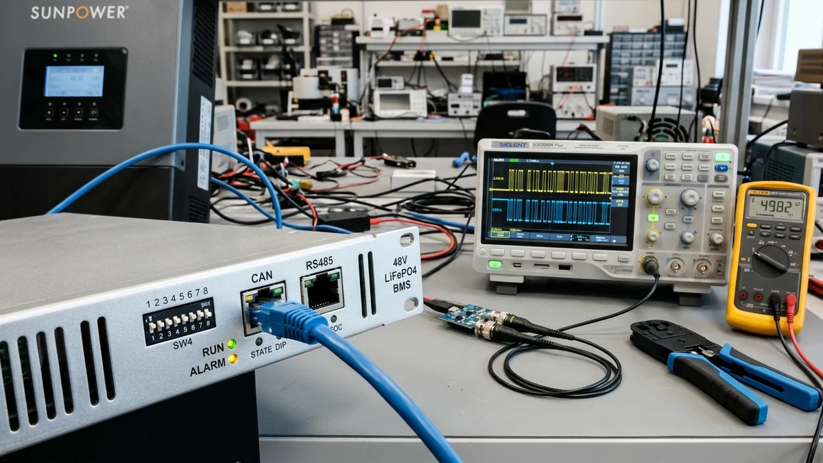
In off-grid and energy storage systems, the communication link between the lithium battery management system (BMS) and the hybrid solar inverter is the single most critical factor determining battery longevity, charging efficiency, and system safety.
Yet, thousands of installers operate their multi-thousand-dollar battery banks in open-loop (lead-acid emulation) mode, relying solely on bulk and float voltage setpoints programmed into the inverter.
Within weeks, open-loop systems experience phantom State-of-Charge (SoC) drift, runner cell voltage cutoffs, and premature inverter shutdowns.
Switching to closed-loop BMS communication transforms the system. By connecting a simple twisted-pair data cable using the Pylontech protocol over CAN bus or RS485, the battery BMS takes command. The inverter becomes an intelligent slave, dynamically adjusting charge currents, cell balancing thresholds, and low-temperature protections millisecond-by-millisecond.
In this comprehensive technical manual, we break down why open-loop control fails, examine CAN versus RS485 physical layers, provide exact RJ45 pinouts for leading hardware brands, detail hardware DIP switch addressing, and share our calibrated laboratory diagnostic isolation protocol.
Closed-loop communication eliminates the 30% SoC drift caused by open-loop voltage sensing. The BMS broadcasts real-time Charge Voltage Limit (CVL), Charge Current Limit (CCL), and Discharge Current Limit (DCL) telemetry packets. If any individual prismatic cell spikes above 3.55V, the BMS commands the inverter to throttle charging amps instantly—preventing high-voltage disconnect trips without user intervention.
Read Cell Balancing Guide →
The Fatal Flaw of Open-Loop Voltage-Based Battery Management
To understand why closed-loop control is mandatory for modern energy storage, technicians must examine the chemical and electrical behavior of lithium iron phosphate ().
The Ultra-Flat LiFePO4 Voltage Plateau
Unlike lead-acid chemistry—where open-circuit voltage declines linearly from 12.8V down to 11.8V as capacity drains— exhibits an extraordinarily flat discharge profile. Between 20% and 80% State of Charge, the open-circuit cell voltage barely moves, hovering between and :
Predictable Voltage Correlation
Every 10% change in capacity produces a noticeable drop in terminal voltage. Inverters can reliably estimate remaining runtime simply by measuring battery bus voltage.
Severe Estimation Drift
A miniscule calibration drift of just () on an inverter voltage sensor represents an enormous 25% to 35% error in calculated State of Charge across the working plateau.
Dynamic Voltage Sag and False Low-Voltage Trips
When high-load appliances start up—such as a well pump, central air conditioner, or air compressor—battery current spikes to .
Internal cell impedance () and cable resistive drops cause immediate terminal voltage sag (). In open-loop mode, the inverter reads this instantaneous drop as an empty battery, triggering an audible alarm or shutting down the inverter completely, even when the battery is at 70% true capacity.
Conversely, during high-amperage solar charging, surface charge pushes terminal voltage up artificially, tricking an open-loop inverter into terminating absorption charging before the cells are fully energized.
Closed-Loop Architecture: The Inverter as a Commanded Slave
Closed-loop communication fundamentally changes the power flow relationship between hardware components. Instead of the inverter guessing battery state from bulk voltage, the battery’s internal microcontrollers send digital telemetry packets every to .
The Four Master Control Parameters
The exact target charging voltage. When all cells are balanced, CVL is set to (). If a single runner cell spikes, the BMS dynamically lowers CVL to to hold absorption without tripping.
Maximum allowable charging amperes. When battery temperature drops below 32°F (0°C), the BMS instantly broadcasts CCL = 0A, stopping solar charging to prevent irreversible lithium plating damage.
Maximum continuous discharge amps. If a multi-pack bank of four batteries loses one module due to maintenance, the BMS reduces DCL proportionally from to , preventing overloading the remaining packs.
Broadcasts high cell voltage, low cell voltage, over-temperature, and short-circuit warning bits. The inverter throttles power smoothly seconds before hardware disconnect relays are forced to trip.
The De-Facto Industry Standard: Pylontech Protocol
While proprietary protocols exist (such as Victron VE.Direct or proprietary EG4/Growatt protocols), the Pylontech protocol (originally developed by Pylon Technologies for the US2000/US3000/US5000 series) has become the universal lingua franca of energy storage.
Almost every tier-1 off-grid and hybrid inverter manufacturer—including Victron Energy, Sol-Ark, Schneider Electric, Deye, Luxpower, EG4, Growatt, and SMA—includes native Pylontech protocol decoding firmware.
CAN Bus vs. RS485: Physical Layer Comparison
Closed-loop communication is physically implemented across one of two serial communication standards: Controller Area Network (CAN) or Recommended Standard 485 (RS485).
| Engineering Parameter | CAN Bus (ISO 11898-2) | RS485 (TIA/EIA-485-A) |
|---|---|---|
| Signaling Method | Differential Voltage (CAN-H & CAN-L) | Differential Balanced Line (A / B or D+ / D-) |
| Common Mode Bias | Nominal (Recessive) | to floating range |
| Dominant State Voltage | Line by | |
| Standard Bit Rates | or | or |
| Bus Arbitration | Non-destructive bitwise (CSMA/CD + AMP) | Polled Master-Slave (Token ring / Modbus) |
| Hardware Error Detection | 15-bit CRC, bit stuffing, frame checks | Software-level parity / Modbus CRC16 |
| Inverter Preference | Tier-1 Inverters (Victron, Sol-Ark, Deye) | Budget Inverters (Legacy Growatt, MPP Solar) |
| Termination Requirement | at each physical end ( net) | termination recommended on long runs |
Why CAN Bus Is Superior for Critical Power Systems
CAN bus was originally engineered by Robert Bosch GmbH for high-noise automotive environments. It possesses three major technical advantages over RS485:
- Hardware-Level Message Arbitration: If two battery packs transmit telemetry simultaneously, the node with the highest-priority identifier (lowest binary ID) wins the bus without garbling the packet.
- Automatic Fault Confinement: If a noisy cable causes transmission errors, the CAN controller automatically isolates the faulty node, preventing the entire inverter comms network from locking up.
- High Bandwidth: Running at (over 25 times faster than standard 9,600 baud RS485), CAN delivers instantaneous microsecond response during rapid load transitions.
RJ45 Cable Pinouts & Crimp Configurations
The single most frequent reason installers encounter communication errors is using a standard straight-through Ethernet patch cord when the inverter requires a custom pinout.
While both sides utilize standard RJ45 modular jacks, the internal pin assignments for CAN-H, CAN-L, RS485-A, and RS485-B vary significantly between equipment manufacturers.
Standard Pylontech Battery BMS RJ45 Pinout
| RJ45 Pin | T568B Wire Color | CAN Function | RS485 Function |
|---|---|---|---|
| Pin 1 | White / Orange | Reserved / NC | RS485-B (Data-) |
| Pin 2 | Orange | GND / Shield | RS485-A (Data+) |
| Pin 3 | White / Green | Reserved / NC | Reserved / NC |
| Pin 4 | Blue | CAN-H (High) | NC |
| Pin 5 | White / Blue | CAN-L (Low) | NC |
| Pin 6 | Green | GND / Shield | GND |
| Pin 7 | White / Brown | NC | RS485-A (Alt) |
| Pin 8 | Brown | NC | RS485-B (Alt) |
Custom Cable Mappings for Major Inverter Brands
When fabricating a custom comms cable, follow these exact pin-to-pin wiring connections:
- Victron Cerbo GX / GX Inverter (Type B Cable):
- Battery Side (Pylontech): Pin 4 (CAN-H), Pin 5 (CAN-L), Pin 2 (GND).
- Victron VE.Can Side: Pin 7 (CAN-H), Pin 8 (CAN-L), Pin 3 (GND).
- Note: Victron uses Pins 7 & 8 on its VE.Can RJ45 port. Plugging a straight-through cable into a Pylontech battery connects Pin 4 to Pin 4, resulting in zero communication.
- Sol-Ark 15K / 18K / Deye:
- Uses standard straight-through cabling for CAN! Pin 4 is CAN-H and Pin 5 is CAN-L on both ends.
- For RS485 Modbus, Sol-Ark reads on Pin 1 (B) and Pin 2 (A).
- EG4 18kPV / 6000XP to EG4 LifePower4 / LL:
- EG4 18kPV CAN port uses Pin 4 (CAN-H) and Pin 5 (CAN-L).
- If using RS485 protocol, use Pin 1 (RS485-B) and Pin 2 (RS485-A).
- Growatt SPF 3000TL / 5000ES:
- Requires setting Inverter Program 05 to
LIand Program 36 toL01(Pylontech protocol). - Uses Pin 1 (RS485-B) and Pin 2 (RS485-A), or dedicated CAN pins depending on hardware revision.
- Requires setting Inverter Program 05 to
Hardware DIP Switch Addressing for Multi-Pack Battery Banks
When multiple 48V server rack batteries are wired in parallel to a common DC busbar, only one single battery is permitted to communicate directly with the inverter. This battery acts as the Master (Pack 1).
All subsequent batteries act as Slaves (Pack 2, Pack 3, etc.). The Master battery aggregates the total capacity, current limits, and alarms from all slave packs across internal Link cables, and then broadcasts a single unified data packet to the inverter.
Binary DIP Switch Addressing Matrix (4-Position Switches)
Configure the 4-pin binary DIP switch on the front panel of each battery module before powering up the bank:
| Battery Role | Address | Switch 1 | Switch 2 | Switch 3 | Switch 4 | Port Connections |
|---|---|---|---|---|---|---|
| Master (Pack 1) | 1 | ON (1) | OFF (0) | OFF (0) | OFF (0) | CAN to Inverter; Link Port 1 to Slave 1 |
| Slave 1 (Pack 2) | 2 | OFF (0) | ON (1) | OFF (0) | OFF (0) | Link Port 0 to Master; Link Port 1 to Slave 2 |
| Slave 2 (Pack 3) | 3 | ON (1) | ON (1) | OFF (0) | OFF (0) | Link Port 0 to Slave 1; Link Port 1 to Slave 3 |
| Slave 3 (Pack 4) | 4 | OFF (0) | OFF (0) | ON (1) | OFF (0) | Link Port 0 to Slave 2; Link Port 1 Empty |
Daisy-Chain Link Cabling Architecture
- Connect the Master Battery’s CAN Port to the Inverter’s BMS/CAN Port using your custom pinout cable.
- Connect a short standard straight-through Ethernet patch cable from Master Link Port 1 to Slave 1 Link Port 0.
- Continue the daisy chain from Slave 1 Link Port 1 to Slave 2 Link Port 0.
- The final slave battery’s Link Port 1 remains unconnected.
- If your battery models feature an internal termination switch (e.g. Switch 6 on 6-position blocks), flip the termination resistor switch to ON only on the Master and the very last Slave module.
Systematic Diagnostic Protocol for Failed BMS Communication
When an inverter displays a communication fault—such as Victron Error #67 (BMS Connection Lost), Sol-Ark F28 (BMS Comm Loss), or Growatt Error 04—use this bench-tested isolation workflow to locate the fault in minutes.
The 60-Ohm Parallel Termination Resistance Test
Turn off all battery breakers and inverter DC disconnects. Unplug the communication cable from the inverter. Using a digital multimeter set to Ohms (Ω), probe between Pin 4 (CAN-H) and Pin 5 (CAN-L) on the disconnected cable plug:
58 Ω – 62 Ω
Perfect. Both 120Ω terminators are active in parallel.
115 Ω – 125 Ω
Missing one terminator. Signals will reflect and cause errors.
> 1,000 Ω or Open
Broken wire, failed crimp, or pinout mismatch.
Live CAN Bus Transceiver Bias Voltage Audit
Reconnect the cable and power on the master battery. Set your multimeter to DC Volts. Measure voltage from CAN pins to battery Ground (Pin 2 or metal chassis):
- CAN-H to Ground: Should read between and DC.
- CAN-L to Ground: Should read between and DC.
- If both pins read , the BMS transceiver chip is unpowered or fried. If both read identically ( static), the bus is in recessive state with zero active transmissions.
Inverter Software Protocol Selection
Enter the inverter touchscreen or web interface. Under battery settings, change battery type from Lead-Acid / Voltage to Lithium / BMS. Select protocol profile: for Victron choose CAN-bus BMS (250 kbit/s); for Sol-Ark choose BMS Lithium 00 (Pylontech); for EG4 choose EG4-CAN or Pylon-CAN.
Strict Order of Power-Up Sequencing
Microcontrollers negotiate addresses strictly upon boot. Power down the entire system completely. Power on Master Battery first and wait 10 seconds. Power on each Slave Battery sequentially. Verify slave RUN LEDs illuminate. Finally, power on the Inverter AC/DC breakers. Within 30 seconds, the inverter screen should display battery telemetry (SoC %, Temperature, Capacity).
Comprehensive Brand Compatibility & Protocol Matrix
Use this quick-reference matrix to pair popular hybrid inverters with common 48V server rack batteries:
| Inverter Model | Battery Model | Recommended Protocol | Physical Port | Required Cable Type |
|---|---|---|---|---|
| Victron MultiPlus-II / Quattro | Pylontech US3000C / US5000 | Pylontech CAN | VE.Can (RJ45) | Victron Type B Cable |
| Victron Cerbo GX | EG4 LifePower4 / LL | Pylontech CAN | VE.Can (RJ45) | Custom Pin 4/5 → 7/8 |
| Sol-Ark 12K / 15K / 18K | Pylontech US5000 | Mode 00 (Pylon) | CAN Port | Standard Straight-Through |
| Sol-Ark 15K / 18K | Trophy / Ruixu / WattCycle | Mode 00 (Pylon) | CAN Port | Standard Straight-Through |
| EG4 18kPV / 6000XP | EG4 LifePower4 / LL-S | EG4 CAN / Pylon | CAN Port | Standard Straight-Through |
| Growatt SPF 5000ES | Pylontech US3000C | LI / Protocol L01 | RS485 Port | Custom Pin 1/2 RS485 Cable |
| Deye SUN-12K-SG04LP3 | Pylontech / Seplos Mason | Pylontech CAN | CAN Port | Standard Straight-Through |
| Schneider Conext XW Pro | Pylontech / Discover AES | Xanbus / Conext Comms | Xanbus Port | Xanbus to CAN Gateway |
Frequently Asked Questions
Can I mix batteries from different brands in a single closed-loop bank?
No. Different manufacturers utilize different BMS chipsets, internal communication baud rates, and cell voltage balancing algorithms. The internal link protocols between master and slave batteries are proprietary. Only parallel identical batteries with identical firmware versions under a single master BMS.
What happens if the communication cable is accidentally unplugged while running?
Tier-1 inverters enter a safety fault mode. If no telemetry packet is received for 60 continuous seconds, the inverter triggers a BMS Comm Loss alarm and automatically reverts to pre-programmed fallback voltage limits or stops charging and discharging completely to prevent overcharging unmonitored cells.
Why does my inverter show 100% SoC while battery cells are still balancing?
In Pylontech protocol, when any individual cell reaches the absorption threshold (), the BMS resets its Coulomb counter and broadcasts 100% SoC to the inverter to initiate current tapering, while active/passive balancers continue bleeding current across high cells.
Is shielded CAT6 cable strictly necessary for closed-loop runs?
For cable lengths under 6 feet (2 meters) inside a metal battery cabinet, unshielded CAT5e/CAT6 is usually sufficient. However, for runs passing near high-frequency inverter DC cables or AC output conduits, Shielded Twisted Pair (STP / FTP) CAT6 with grounded metal RJ45 plugs is strongly recommended to eliminate electromagnetic switching noise interference.