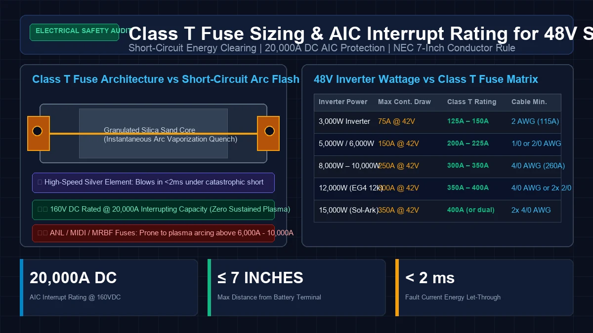
When assembling a 48V residential energy storage system, DIY builders and certified solar installers often invest thousands of dollars into high-capacity LiFePO4 server rack batteries or DIY prismatic cell banks. Yet, the single most critical safety component in the entire DC distribution network is a small ceramic cartridge that costs under $60: the Class T main battery fuse.
Direct current (DC) battery circuits present an extreme electrical hazard that alternating current (AC) grid circuits do not share. In an AC grid system, the sine wave crosses zero volts 100 to 120 times every second, allowing standard circuit breakers and budget fuses to extinguish electrical arcs naturally. In a 48V DC lithium circuit, current flows continuously with zero voltage crossings.
If a dropped wrench, failed inverter input capacitor, or crushed conductor creates a dead short across your battery terminals, the stored electrochemical energy discharges with explosive violence. A standard automotive fuse will not blow cleanly; instead, it will vaporize, ionize the surrounding air into 6,000°F plasma, and weld its contacts together, feeding continuous fault current until battery cells rupture in thermal runaway.
At GridSpecLab, our electrical engineers conducted exhaustive benchmarking on DC overcurrent protection devices. In this guide, we break down the physics of lithium short-circuit currents, compare the Ampere Interrupting Capacity (AIC) of Class T versus ANL, MRBF, and MEGA fuses, provide an exact inverter sizing table from 3kW to 15kW, and outline the NEC 7-inch installation rules.
Mandatory Requirement: Every 48V lithium iron phosphate (LiFePO4) battery system connected to a common DC bus or hybrid inverter exceeding 3,000W must have a UL-listed Class T fuse rated for at least 20,000A AIC at 125V/160V DC. Standard ANL, MIDI, and automotive circuit breakers lack the arc-extinction capability required for lithium fault currents and create severe arc-flash fire hazards. Install the Class T fuse within 7 inches of the battery positive terminal, sized at 125% of the inverter’s maximum continuous DC input current.
Catastrophic Short-Circuit Current in Lithium Battery Banks
To understand why a specialized fuse is mandatory, you must calculate the prospective short-circuit current () of modern prismatic lithium iron phosphate cells (such as Eve LF280K, Eve MB31, or CATL 302Ah).
Traditional lead-acid golf cart or AGM batteries have relatively high internal resistance ( per 12V block). A 48V lead-acid bank rarely generates short-circuit currents greater than 2,500A to 4,000A.
In contrast, Grade-A 3.2V 280Ah LiFePO4 prismatic cells feature an internal AC impedance () of less than , with a DC internal resistance of roughly . When you connect sixteen cells in series to create a 51.2V nominal battery pack, the total cell resistance is:
Adding the resistance of fifteen copper busbars () and internal BMS shunts (), the entire internal loop resistance of a single 48V 280Ah pack is under ().
Applying Ohm’s Law for a bolting dead-short directly at the pack terminals:
When two or three 48V server rack batteries (e.g., EG4 LL-S, SOK, Pytes V5, or Ruixu) are wired in parallel to a common Lynx Distributor or busbar, internal resistances drop in parallel, and prospective short-circuit current surges past 20,000 to 25,000 Amperes:
At 30,000 Amps, thousands of joules of magnetic and thermal energy () are dumped into the fault in less than five milliseconds. The conductor experiences mechanical magnetic forces powerful enough to tear copper busbars off their studs, while vaporizing metal instantly.
Understanding Ampere Interrupting Capacity
Every fuse and circuit breaker carries two completely distinct electrical ratings:
- Continuous Current Rating (Amperes): The current the fuse can carry indefinitely at its rated ambient temperature without melting its internal element (e.g., 200A, 300A, 400A).
- Ampere Interrupting Capacity (AIC) / Interrupt Rating (IR): The maximum short-circuit fault current that the overcurrent device can safely interrupt without physically exploding, cracking its casing, or sustaining a continuous electric plasma arc across the open gap.
+-----------------------------------------------------------------------------+
|                      AIC (INTERRUPT RATING) COMPARISON                      |
|                                                                             |
| Class T Fuse (UL Listed)                                                    |
| [==================================================] 20,000A DC @ 160V     |
|                                                                             |
| MRBF Fuse (Marine Rated Battery Fuse)                                       |
| [=========================] 10,000A DC @ 14V (Drops to ~2,000A at 58V)      |
|                                                                             |
| ANL Fuse (Automotive Audio / Inverter)                                      |
| [===============] 6,000A DC @ 32V (Unrated / Unsafe at 58V DC)              |
|                                                                             |
| Thermal Circuit Breaker (Budget Amazon / Marine)                            |
| [=====] 1,500A to 3,000A DC (Contacts weld shut instantly)                 |
+-----------------------------------------------------------------------------+
The Plasma Arc Hazard in Direct Current Circuits
When a fuse blows under normal overload conditions (e.g., 250A on a 200A fuse), the element heats up slowly, melts, and opens the circuit cleanly.
However, during a 15,000A lithium dead short, the metallic element does not simply melt—it undergoes instantaneous phase transition into an ionized metallic vapor. In an AC circuit, this plasma cools and extinguishes as the voltage drops through the zero-volt axis.
In a 48V to 58.4V DC circuit, the voltage never drops to zero. The 58 volts of DC potential easily ionizes the vaporized copper or zinc, creating an electric arc that burns at temperatures exceeding 6,000°F (hotter than the surface of the sun). If the fuse housing cannot contain this pressure and physically quench the arc, the plasma bridges the terminal studs, allowing tens of thousands of amps to continue flowing through the air until the battery wiring burns completely through.
Fuse Architecture Comparison: Class T vs ANL vs MRBF
To evaluate the mechanical and electrical suitability of each overcurrent device for 48V energy storage, let us examine their internal construction:
| Fuse Category | Standard AIC Rating | Max DC Voltage | Internal Arc Quenching Medium | Speed of Operation | Suitable for 48V LiFePO4? |
|---|---|---|---|---|---|
| Class T (JLLN / JJN) | 20,000A DC | 125V / 160V DC | Compacted Granular Silica Sand | Extremely Fast (less than 2 ms) | Yes (Gold Standard) |
| MRBF (Marine Battery) | 10,000A @ 14V (under 2,000A @ 58V) | 58V DC | Air gap with ceramic insulator | Fast Acting | Single Small Pack Only |
| ANL Fuse | 2,700A – 6,000A | 32V (some 80V) | Open air / Mica sheet | Moderate (Time-delay) | No (Severe Hazard) |
| MEGA / MIDI Fuse | 2,000A | 32V / 58V | Clear plastic / Open air | Slow-Blow | No (Sub-panel only) |
| Budget DC Breaker | 1,500A – 3,000A | 48V – 60V | Mechanical air contact separation | Slow (10–50 ms) | No (Contacts Weld) |
Why Class T Fuses Dominate High-Capacity DC Protection
The superior performance of UL Class T fuses (such as Littelfuse JLLN, Eaton Bussmann JJN, or Blue Sea Systems Class T series) is rooted in three mechanical engineering factors:
- Compacted Silica Sand Core: The high-purity silver element is suspended inside a heavy ceramic body surrounded by densely packed, fine-grain silica sand. When a catastrophic fault vaporizes the silver element, the high-pressure plasma arc is instantly forced into contact with the cold silica grains. The sand instantly melts into a non-conductive glass matrix (fulgurite), absorbing the thermal energy and suffocating the electric arc in less than 2 milliseconds.
- Current-Limiting Characteristics: A Class T fuse is a true current-limiting device. Under massive short-circuit conditions, it clears so rapidly that the prospective fault current never reaches its theoretical peak. This drastically reduces the total clearing energy delivered to downstream inverter MOSFETs and battery cells.
- High DC Voltage Withstand: While cheap fuses are rated for 32V DC (suitable only for 12V or 24V systems), authentic Class T fuses carry certified UL ratings of 125V DC or 160V DC, easily containing the 58.4V absorption charging voltages of 16S LiFePO4 chemistry.
Inverter Wattage to Class T Fuse Sizing Matrix
A common dilemma for solar installers is selecting the exact fuse ampacity. If you size the fuse too close to the inverter’s rated continuous wattage, normal temporary surge loads (such as starting a 5-ton geothermal heat pump or well pump) will prematurely fatigue the fuse element and cause nuisance tripping.
If you size the fuse too large, the fuse will fail to protect the conductor, allowing the cable insulation to melt before the fuse blows.
Sizing Mathematical Formula
To calculate the minimum fuse rating, determine the inverter’s maximum continuous DC current at lowest battery cutoff voltage, factoring in inverter conversion efficiency ():
Where:
- = Continuous inverter AC output power (Watts)
- = Inverter full-load DC-to-AC conversion efficiency (typically )
- = Lowest operational DC battery voltage before inverter shutdown (typically to )
To comply with NEC Section 690.8 / 705.12 for continuous duty (loads running for 3 hours or more), apply a 125% safety multiplier:
48V Inverter Class T Sizing Reference Table
The following table provides verified, code-compliant Class T fuse ratings, expected DC currents, and corresponding minimum conductor sizes for popular 48V hybrid and off-grid inverters:
| Inverter Power Rating | Example Hardware Models | Max Continuous DC Current (@ 42V Cutoff) | NEC 125% Continuous Rule | Recommended Class T Fuse Rating | Minimum Pure Copper Cable Gauge (75°C / 90°C) |
|---|---|---|---|---|---|
| 3,000 Watts | Victron MultiPlus-II 48/3000, Growatt SPF 3000TL | 78 Amperes | 97.5 Amperes | 125A – 150A | 2 AWG (115A / 130A) |
| 5,000 Watts | Growatt SPF 5000ES, SRNE 5kW | 130 Amperes | 162.5 Amperes | 175A – 200A | 1/0 AWG (150A / 170A) |
| 6,000 Watts | EG4 6000XP, MidNite Rosie 7048 | 155 Amperes | 193.8 Amperes | 200A – 225A | 2/0 AWG (175A / 195A) |
| 8,000 Watts | SunGoldPower 8kW, Deye 8kW Split-Phase | 207 Amperes | 258.8 Amperes | 250A – 300A | 4/0 AWG (230A / 260A) |
| 10,000 Watts | SRNE 10kW Hybrid, Deye 10kW | 259 Amperes | 323.8 Amperes | 350A | 4/0 AWG or Parallel 2x 1/0 |
| 12,000 Watts | EG4 12000XP, Schneider Conext XW Pro (Dual) | 310 Amperes | 387.5 Amperes | 400A | Parallel 2x 2/0 AWG |
| 15,000 Watts | Sol-Ark 15K, EG4 18kPV, Deye 16kW | 388 Amperes | 485.0 Amperes | Dual 250A (or Single 500A) | Parallel 2x 4/0 AWG |
[!IMPORTANT] Cable Coordination Rule: The continuous ampacity rating of your DC battery conductors must always be equal to or greater than the rating of the Class T fuse protecting them. If you install a 400A Class T fuse, your battery conductors must be rated for at least 400A (e.g., dual parallel runs of 2/0 AWG or 4/0 AWG Class K copper). Never install a 400A fuse on a single 1/0 AWG wire.
The NEC Seven-Inch Conductor Rule and Mounting Standards
Selecting the correct fuse rating is only half the battle; physical placement determines whether the fuse can actually prevent a structural fire.
National Electrical Code Requirements (NEC Article 705 & ABYC E-11)
Under NEC 705.12 and ABYC standard E-11 (AC and DC Electrical Systems on Boats, universally adopted by high-end off-grid solar engineers):
- The 7-Inch Rule: Overcurrent protection must be placed within 7 inches (178 mm) of conductor length from the point of connection to the DC power source (the battery terminal or common positive busbar).
- The 40-Inch Sheath Exception: If the conductor between the battery positive terminal and the fuse holder is enclosed in a continuous protective conduit, heavy-duty wire loom, or secondary protective sheath, the distance may be extended to a maximum of 40 inches (1.02 meters).
+-----------------------------------------------------------------------------+
|               CORRECT CLASS T FUSE INSTALLATION TOPOLOGY                    |
|                                                                             |
| [ 48V Battery Bank ]                                                        |
|   (+) Positive Terminal                                                     |
|      |                                                                      |
|      | === Under 7 Inches Pure Copper Conductor ===                             |
|      v                                                                      |
|  [ Class T Fuse Block with Polycarbonate Cover ]                            |
|      |                                                                      |
|      | === Primary 4/0 AWG Feeder Cable ===                                 |
|      v                                                                      |
|  [ 2-Pole Heavy-Duty DC Disconnect Switch ]                                 |
|      |                                                                      |
|      v                                                                      |
|  [ 48V Hybrid Inverter DC Input Terminals ]                                 |
+-----------------------------------------------------------------------------+
Why the 7-Inch Rule Exists
Any segment of battery cable located between the battery terminal and the fuse is completely unprotected. If that short piece of cable rubs against a metal battery rack, is pinched by a steel door, or has its insulation compromised, the full 20,000A fault current will dump unrestricted into the short. Keeping this unprotected lead under 7 inches minimizes the geometric area where an unfused short-circuit can physically occur.
Fuse Block Selection Criteria
Never attempt to mount a Class T fuse using loose nuts and washers on standard bolts. Authentic Class T fuses require specialized high-amperage fuse blocks (such as the Blue Sea Systems 5502 for 110A–200A fuses or Blue Sea Systems 5503 for 225A–400A fuses). These blocks feature:
- Heavy Tin-Plated Copper Busbars: Capable of dissipating heat generated by continuous full-load currents without degrading.
- Precision Stud Alignment: Class T fuses have unique slotted mounting tabs that require precise stud spacing (e.g., 2.0 inches for small bodies, 2.43 inches for large bodies).
- Flame-Retardant Polycarbonate Covers: Clear protective insulating covers that satisfy OSHA and NEC finger-safe requirements, preventing accidental contact with metal tools while allowing visual inspection of the fuse indicator.
Step-by-Step Fuse Installation and Commissioning Protocol
Installing a Class T fuse into an energized 48V lithium battery bank requires meticulous attention to safety protocols:
Preparation and Tool Safety
Before approaching the battery bank, remove all metallic jewelry, watches, and rings. Wear safety glasses with side shields and use electrically insulated hand tools rated for 1,000V (IEC 60900 compliant).
Mounting and Mechanical Assembly
- Mount the Fuse Block Securely: Fasten the Class T fuse block to a non-conductive, fire-resistant backboard (such as 3/4-inch marine plywood painted with fire-retardant paint or cement backer board). Ensure it is positioned within 7 inches of the battery master positive disconnect or terminal stud.
- Fabricate the Interconnect Cable: Cut a segment of high-strand Class K tinned copper cable (2/0 AWG or 4/0 AWG). Strip the insulation cleanly without nicking strands, slide dual-wall adhesive heat shrink tubing over the jacket, and crimp heavy-duty closed-end tinned copper lugs using a calibrated hydraulic hex die crimper.
- Assemble the Stud Stack Properly: Place the cable lug directly against the tin-plated copper base of the fuse block. Next, place the Class T fuse mounting tab directly on top of the lug. Add the flat washer, split lock washer, and brass/stainless nut.
- Torque to Manufacturer Specification: Never guess fastener torque. Using a calibrated inch-pound torque wrench, tighten the 5/16” or 3/8” terminal nuts to 130 to 150 in-lbs (14.7 to 17.0 N·m). Loose fuse connections create high electrical resistance (), leading to thermal runaway of the fuse block and nuisance thermal tripping under normal loads.
Inverter Pre-Charge Sequence Before Energizing
When connecting a 48V battery bank to an inverter for the first time, large uncharged electrolytic capacitors inside the inverter input stage act as an instantaneous short circuit. If you throw the main disconnect switch directly onto uncharged capacitors, the instantaneous inrush current can exceed 1,000A for a fraction of a millisecond.
While a Class T fuse will usually survive this quick inrush pulse, the arc will pit the disconnect breaker contacts and can trip sensitive battery BMS protection boards into latch-up fault mode. Always bridge a 30-ohm to 50-ohm 50W wirewound pre-charge resistor across the disconnect switch contacts for 5 seconds before closing the main breaker.
Critical Safety Mistakes to Avoid in DIY Battery Banks
Through dozens of independent hardware audits on DIY solar installations, the GridSpecLab engineering team has documented four dangerous mistakes regarding battery fuses:
Installing Fuses on the Negative Conductor
Fuses should always be installed on the ungrounded positive conductor. If a fuse is installed on the negative cable in a system where the inverter chassis or battery enclosure is tied to earth ground, a short between the positive conductor and the chassis will bypass the negative fuse entirely, feeding unlimited current through equipment grounding conductors.
Relying Exclusively on the Battery BMS for Overcurrent Protection
Many DIY builders believe that because their server rack battery contains a Smart BMS (such as JK, JBD, Daly, or Seplos) with electronic overcurrent protection, an external fuse is redundant.
This assumption is dangerously flawed. A BMS relies on solid-state N-channel MOSFET switches to interrupt current. During an extreme short-circuit fault with rise times () of microseconds, the massive gate-to-drain voltage transient routinely punches through the MOSFET silicon junction, causing the transistors to fail shorted (permanently closed) in less than 50 microseconds. An electro-mechanical Class T fuse is the mandatory fail-safe that guarantees physical circuit severance when semiconductors melt.
Using Cheap Car Audio Fuses and Fuse Holders
Budget gold-plated ANL fuse blocks purchased from automotive audio retailers utilize low-melting-point plastic bases and thin stamped brass tabs. Under sustained loads of 150A to 200A, these holders overheat, soften, warp, and cause catastrophic electrical fires long before the fuse element ever reaches its blowing threshold.
Omitting the Polycarbonate Shield
Leaving the conductive copper studs of a Class T fuse exposed inside a battery cabinet is an invitation for disaster. Dropping an uninsulated ratchet or screwdriver across the terminals will create an arc flash right at the fuse. Always install the manufacturer’s heavy clear polycarbonate insulating cover immediately following torque verification.
Frequently Asked Questions
What is the difference between a Class T fuse and a Class J fuse?
Both Class T and Class J fuses offer 20,000A to 200,000A interrupting ratings. However, Class T fuses are physically much more compact (approximately half the size of Class J), have zero time-delay, and offer significantly faster current-limiting action, making them the standard choice for DC battery systems where space inside power distribution boxes is limited.
Can I use an ANL fuse if my inverter is only 3,000 Watts?
While a 3,000W inverter draws around 75A continuously, the fuse is there to protect against battery short circuits, not just inverter overloads. If your battery bank consists of 280Ah LiFePO4 cells capable of delivering 10,000A fault current, an ANL fuse (rated for only 2,700A–6,000A AIC) remains an extreme fire and arc hazard regardless of inverter size.
Should I install a Class T fuse on each parallel battery or on the main inverter feeder?
The most robust design employs a two-tier protection strategy:
- An individual overcurrent protection device (such as an MRBF or Class T fuse sized at 150A–200A) on each individual battery string before it joins the common busbar.
- A single main master Class T fuse (sized for the full inverter continuous load, e.g., 300A–400A) on the main positive conductor between the busbar and the inverter.
Summary and Laboratory Recommendations
A catastrophic DC short circuit is the single most destructive event that can occur in a residential solar energy storage system. By installing an authentic, UL-listed Class T fuse rated for at least 20,000A AIC at 125V/160V DC within 7 inches of your battery positive terminal, you ensure that any downstream electrical fault is extinguished in milliseconds without fire, explosion, or sustained arc flash.
For further wiring and battery system sizing engineering audits, explore our companion guides on 4/0 AWG vs 2/0 AWG Battery Cable Sizing for 48V Inverters and DC Breakers and Fuses for Solar Battery Systems.