While the municipal electrical grid operates on Alternating Current (AC), the modern renewable energy revolution is powered almost entirely by Direct Current (DC).
Every photon of sunlight absorbed by a silicon solar panel excites electrons into a unidirectional direct current. Every chemical reaction inside a lithium iron phosphate (LiFePO4) battery stores and releases energy as DC. And every smartphone, laptop, LED diode, and electric vehicle drivetrain relies on DC power to function.
Yet many off-grid homeowners, RV travelers, and emergency preppers needlessly convert DC battery power into 120V AC through an inverter—only to plug in an AC wall brick that converts the power right back into DC! This double-conversion cycle wastes between 15% and 30% of your valuable stored energy as useless heat.
This engineering guide demystifies Direct Current: how it behaves at the atomic level, how solar cells and battery storage banks produce steady voltage, how native DC microgrids boost efficiency, and why high-voltage DC requires specialized safety equipment to prevent lethal electrical fires.
The Core Rule: Direct Current flows in a single direction with zero oscillation (0 Hz), making it ideal for chemical battery storage and digital electronics. To maximize off-grid battery runtime, power small continuous loads (refrigeration, routers, USB-C laptops) directly from native DC distribution rather than running an oversized AC inverter 24/7. Never use standard AC circuit breakers on high-voltage DC solar strings—DC arcs do not self-extinguish and require dedicated DC-rated breakers with magnetic arc chutes.
Deconstructing Direct Current: Physics and Electron Flow
At the subatomic level, electric current is the net movement of free charge carriers—predominantly negatively charged electrons—through a conductive medium such as copper wire:
Where:
- = Electric current measured in Amperes (1 Ampere = 1 Coulomb of charge per second)
- = Quantity of electrical charge in Coulombs ( electrons)
- = Elapsed time in seconds
Direct Current (DC) Profile
Voltage remains constant at a fixed potential difference. Electrons drift continuously in one direction from negative to positive terminals.
Key Advantage: No inductive phase lag (), eliminating reactive power losses found in alternating current circuits.
Alternating Current (AC) Contrast
Voltage alternates continuously along a trigonometric sine curve, crossing zero volts 120 times per second in North American electrical systems.
Grid Benefit: Easily stepped up to ultra-high voltages (500kV+) using passive electromagnetic transformers for bulk long-distance wheeling.
How Solar Panels and Batteries Generate DC Electricity
The clean energy ecosystem produces DC power through two distinct physical mechanisms:
The Photovoltaic Effect in Solar Cells
Solar panels generate Direct Current through semiconductor physics. A silicon solar cell consists of two distinct layers: an n-type layer doped with phosphorus (extra electrons) and a p-type layer doped with boron (missing electrons or “electron holes”).
- At the junction between the layers, a permanent built-in electrostatic field forms.
- When photons of sunlight strike the silicon crystal, they transfer energy to bound electrons, knocking them free.
- The internal electric field forces these free electrons to travel in one single direction—toward the front metal contacts.
- When a closed circuit is connected, electrons flow through your external cabling, into the charge controller, and return to the back layer. Because the electrostatic field only pushes electrons in one direction, the output is pure, non-oscillating Direct Current.
Electrochemical Reactions in LiFePO4 Batteries
A chemical battery does not store raw electricity; it stores chemical potential energy.
Inside a Lithium Iron Phosphate (LiFePO4) cell, lithium ions () reside in the cathode during a discharged state. When charging, an external DC voltage forces lithium ions to migrate through a liquid electrolyte into the porous graphite anode.
During discharge:
- Spontaneous oxidation releases electrons at the negative anode.
- Because the internal electrolyte blocks free electrons, they are forced to flow through your external copper wires to power your appliances before recombining at the positive cathode.
- This chemical reaction creates a steady, predictable Direct Current voltage (nominally 3.2V per cell, or 51.2V across a 16-cell series solar battery pack).
The Efficiency Dividend: Native DC-to-DC Microgrids
In a conventional off-grid solar installation, a staggering amount of energy is wasted through repetitive power conversions:
The Conventional Double-Conversion Trap
When you run a laptop charger or 12V cooler through an AC inverter, you lose up to 35% of your stored battery capacity in conversion heat and inverter idle tare loss!
The Native DC Alternative
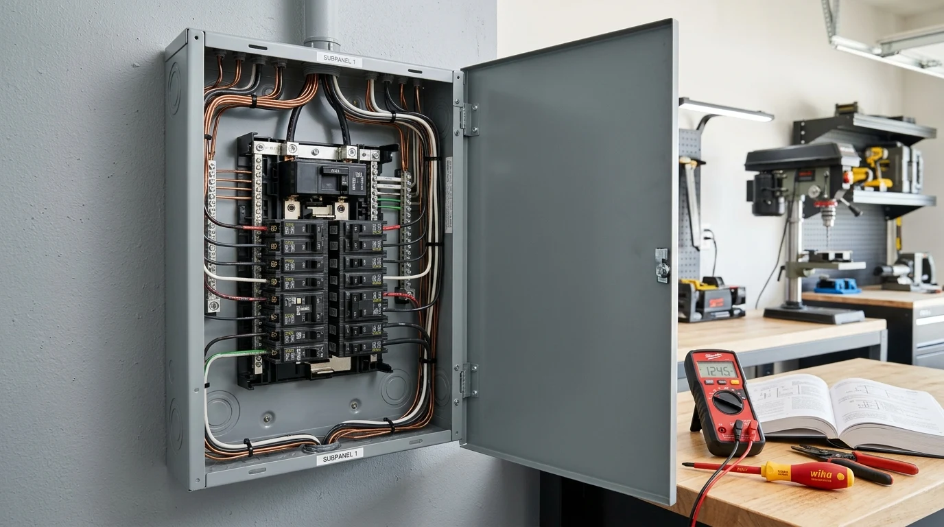
By wiring a dedicated DC subpanel (using 12V, 24V, or 48V-to-12V buck converters), you power native DC loads directly from the battery bank:
- 12V / 24V Danfoss/Secop Compressor Refrigerators: Uses 35W to 45W only when cycling; consumes 0W idle.
- 100W USB-C Power Delivery (PD) Ports: Directly charges MacBooks, drones, and camera batteries at 95%+ efficiency.
- Starlink & Internet Routers: Modified with native DC-DC power supplies, cutting 24-hour energy consumption from 1,200Wh down to under 550Wh!
- LED Lighting Strips: Driven directly from DC buck regulators without AC humming or flicker.
This enables you to completely switch your main 3,000W or 6,000W AC inverter OFF for 16 to 18 hours per day, saving 500Wh to 1,200Wh in vampire tare loss.
The Non-Extinguishing DC Arc: Why DC Arcs Are Dangerous
The most critical safety distinction between AC and DC electricity is how they behave during an accidental disconnect or fault condition:
Because 60Hz AC voltage alternates through zero volts 120 times each second, the plasma arc cools and naturally collapses at every zero-crossing point.
Standard switches quench AC arcs easily.DC voltage never crosses zero. If you disconnect an energized 300V DC solar cable or 48V battery circuit under load, the arc sustains continuously across the air gap at 5,000°F (2,760°C).
Vaporizes copper contacts and causes structure fires.[!WARNING] Never use AC-rated circuit breakers or household light switches on DC circuits! AC circuit breakers lack the permanent magnetic blowout coils and multi-plate arc splitter chutes required to stretch and extinguish a continuous DC plasma arc. A high-voltage DC fault across an AC breaker will weld the internal contacts closed and ignite the electrical panel.
Critical DC Power System Mistakes to Avoid
When designing and wiring direct current circuits, avoid these four catastrophic mistakes:
Accidental Reverse Polarity Without Diode Clamping
Unlike AC circuits where hot wires alternate, connecting a DC solar array or battery bank with reverse polarity (positive to negative) instantly creates an uncontrollable dead short. Internal protection diodes will vaporize, capacitor banks will explode, and motherboard PCB traces will burn out in milliseconds. Always color-code wiring meticulously (Red for Positive, Black for Negative) and verify with a digital multimeter before closing breakers.
Undersizing High-Current DC Busbars
In 12V and 24V systems, amperage is enormous. Powering a 3,000-watt inverter from a 12V battery bank pulls 250 Amps of continuous direct current. Connecting multiple battery cables to a single stud using a stack of ring terminals creates severe contact resistance, heating the stud to over 200°F. Always use heavy solid copper busbars rated for a minimum of 250A to 500A.
Skipping Catastrophic Class-T Fusing on Lithium Batteries
Modern LiFePO4 batteries feature internal short-circuit protection in their Battery Management System (BMS). However, if an external screwdriver drops across positive and negative busbars, the battery can unleash a short-circuit current exceeding 10,000 to 20,000 Amps before the BMS MOSFETs can react—causing the MOSFETs to weld shut into a permanent short.
You must install a Class-T or NH-type catastrophic fuse rated for at least 20,000 Amps Interrupting Capacity (AIC) directly on the positive battery terminal post.
Ignoring Voltage Drop in Low-Voltage DC Runs
Because voltage drop is directly proportional to current, pushing 20 Amps through a 12V line results in sixteen times more percentage voltage drop than pushing 5 Amps through a 48V line. Sizing DC cables without running a round-trip voltage drop calculation will choke charge controllers and trigger premature low-voltage cutouts.
Top Recommended DC Power & Measurement Hardware
To ensure your DC solar and battery systems operate safely and at peak electrical efficiency, our lab recommends the following equipment:
1. High-Density Server-Rack DC Battery: EG4 LifePower4 V2 (48V 100Ah)

EG4 LifePower4 V2 48V (51.2V 100Ah LiFePO4 Server Rack Battery)
Engineered for high-efficiency DC microgrids and whole-home solar storage. Features Tier-1 prismatic cells, integrated 100A DC thermal-magnetic breaker, and closed-loop BMS communication over CAN/RS485.
Explore EG4 LifePower4 Pricing →
2. Digital True-RMS DC Clamp Multimeter: Klein Tools CL800
Klein Tools CL800 Auto-Ranging Digital AC/DC Clamp Meter
Standard clamp meters only read alternating magnetic fields from AC. The CL800 incorporates integrated Hall Effect sensors capable of measuring direct current (DC) up to 600A non-intrusively around a single conductor.
View Klein CL800 Clamp Meter →
Interactive Sizing and Runtime Calculators
Optimize your direct current system design using our interactive engineering tools:
- Solar Generator Runtime Calculator: Calculate true runtime when powering DC vs. AC loads.
- Solar Cold Temperature Voltage Calculator: Calculate maximum open-circuit DC voltage on freezing mornings to protect MPPT controllers.
- Inverter Tare Loss Calculator: Calculate how much battery capacity you save by switching to native DC circuits.
Frequently Asked Questions (FAQ)
Is DC power safer or more dangerous than AC power?
Both can be lethal at high voltages. AC electricity is particularly dangerous to the human heart because 50Hz and 60Hz frequencies disrupt the natural cardiac rhythm, triggering ventricular fibrillation at lower currents (50mA to 100mA). However, DC electricity causes continuous, tetanic muscle contractions (freezing your hand to the conductor) and creates severe, deep electrochemical burns. In addition, DC arcs do not self-extinguish, posing a substantially higher fire hazard.
Why do cars use 12V DC systems?
Historically, 12V DC was chosen as the optimal balance for automotive lead-acid batteries: low enough to prevent any electric shock hazard to mechanics (voltages under 60V DC are considered touch-safe), high enough to crank small starter motors, and simple to wire without conduit. Modern electric vehicles, however, utilize 400V to 800V DC architectures to slash copper wire weight and enable ultra-fast 350kW charging.
Can I run my Starlink satellite internet dish directly on DC?
Yes. Starlink terminals (both Gen 2 Standard Actuated and Gen 3 Standard) internally operate on direct current (typically 48V to 56V DC via Power over Ethernet). By using an aftermarket DC-DC step-up converter and passive PoE injector, you can eliminate the factory Starlink AC router, saving roughly 20W to 30W of continuous inverter power (up to 700Wh per day).
What does “floating DC ground” mean in a solar system?
In an ungrounded or floating DC system, neither the positive nor the negative solar conductor is bonded to the chassis earth ground. Both conductors operate with balanced electrical insulation. Modern transformerless grid-tie and hybrid inverters require floating DC arrays and rely on sensitive Ground Fault Protection (GFP) and Insulation Resistance (Riso) detection circuits to instantly shut down if a conductor contacts earth ground.
