Among modern power conversion hardware, the Victron Energy MultiPlus-II stands out for its industrial-grade low-frequency toroidal transformer, its ultra-fast 0ms UPS transfer switch, and its open software ecosystem. However, for DIY installers and commissioning engineers opening Victron’s legacy VEConfigure 3 software for the first time, one architectural fork causes more confusion than any other setting:
Should you use the Virtual Switch, or should you configure Assistants?
Both tools allow you to automate the MultiPlus-II’s internal AC input transfer relay, its programmable auxiliary dry contacts, and its multi-stage battery charger. Yet they operate on completely different firmware logic engines. Choosing the wrong path can leave your generator refusing to auto-start during a deep winter freeze, cause your grid connection to disconnect erratically, or lock you out of advanced features like ESS (Energy Storage System) grid-parallel peak shaving.
This engineering guide demystifies the fundamental architectural differences between the Virtual Switch and VEConfigure Assistants, walks through complete real-world configuration scripts for auto-generator starting and solar thermal diversion, and outlines the exact protocols for flashing settings via local MK3-USB adapters or the cloud-based VRM Portal.
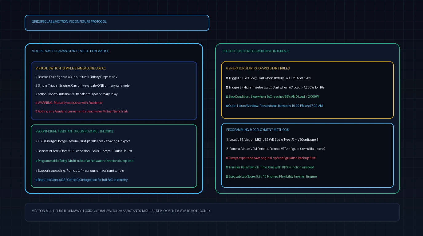
In Victron’s microprocessor firmware, the Virtual Switch and Assistants share the exact same internal RAM execution space. You cannot blend them. The moment you add even a single Assistant (such as the ESS Assistant or a Programmable Relay script), the Virtual Switch tab in VEConfigure 3 is permanently disabled and hidden from view. If you need multi-conditional logic, you must build the entire control tree inside the Assistants framework.
Architectural Comparison: Virtual Switch vs Assistants
To understand why Victron maintains two distinct control engines inside the MultiPlus-II, consider how firmware automation has evolved over the past two decades.
┌────────────────────────────────────────────────────────┐
│ VICTRON VE.BUS MICROCONTROLLER FIRMWARE               │
│                                                        │
│  [ OPTION A: VIRTUAL SWITCH ENGINE ]                   │
│   • Single-Trigger / Single-Action                     │
│   • Hardcoded firmware branch                          │
│   • No external sensor / Cerbo GX SoC awareness        │
│                       ── OR ──                         │
│  [ OPTION B: ASSISTANTS EXECUTION STACK ]             │
│   • Multi-conditional algorithmic scripts (Up to 14)   │
│   • Reads Cerbo GX / Pylontech / CAN-bus Battery SoC%  │
│   • Cascading logic: ESS, Gen-Start, Dump Loads        │
└────────────────────────────────────────────────────────┘
The Virtual Switch: Simple Single-Variable Logic
The Virtual Switch is an integrated firmware routine developed for simple, isolated systems without external monitoring computers. It allows the inverter to evaluate one primary input condition (such as DC battery voltage, AC load wattage, or a physical digital input switch) and execute one primary hardware action (such as opening the internal AC input transfer switch to ignore the utility grid, or toggling the internal auxiliary relay).
When the Virtual Switch is Appropriate:
- Basic Off-Grid Cabin: You want the MultiPlus-II to run 100% on battery and solar during the day, and connect to a utility line or backup generator only when battery voltage sags below for 60 seconds.
- Marine Shore Power Switch: You want to connect to marina shore power only when you physically flip a manual rocker switch connected to the Aux 1 digital input terminals.
- Standalone Inverter (No Cerbo GX): You do not have a GX device (Cerbo GX, Ekrano GX, or Venus OS on Raspberry Pi) and rely solely on the inverter’s internal voltage measurements.
VEConfigure Assistants: Multi-Conditional Algorithmic Scripting
Assistants are modular, microprocessor-level software routines compiled into the MultiPlus-II’s non-volatile memory. Victron permits up to 14 individual Assistants to run concurrently in a priority-stacked sequence.
Unlike the Virtual Switch, Assistants can combine Boolean logic (AND / OR gates), read complex multi-node network variables over the VE.Bus (such as true Battery State-of-Charge percentage from a smart BMS over CAN-bus), and handle complex timing hysteresis loops.
When Assistants are Mandatory:
- ESS (Energy Storage Systems): Grid-tied self-consumption, zero-feed-in export limiting, and dynamic time-of-use tariff arbitrage.
- Advanced Generator Control: Starting a generator based on both low SoC% (under 20%) AND high AC load demand (over 4,000W), while enforcing quiet-hours lockouts between 10:00 PM and 7:00 AM.
- Excess Solar Diversion: Energizing a solid-state relay to power a domestic hot water tank heating element when batteries reach 98% SoC and solar production exceeds household loads.
- Frequency Shifting AC-Coupling: Controlling grid-tie microinverters (Enphase) or string inverters (Fronius) connected to the MultiPlus-II’s AC-Out-1 port during an off-grid blackout.
Comparative Feature Matrix
| Functional Capability | Virtual Switch | VEConfigure Assistants |
|---|---|---|
| Simultaneous Logic Scripts | Single Condition Only | Up to 14 Stacked Assistants |
| Battery State-of-Charge (SoC%) Awareness | No (Voltage & Time Only) | Yes (Reads BMS via Cerbo GX) |
| Grid-Parallel ESS Operation | No | Yes (ESS Assistant Mandatory) |
| Multi-Condition Boolean Logic (AND/OR) | No | Yes (Fully Configurable) |
| Quiet Hours Generator Lockout | No | Yes (Integrated Time Constraints) |
| Firmware Memory Footprint | Zero (Built into base code) | Allocates flash memory slots |
| Remote Programming via VRM | Supported | Supported |
Configuring the Virtual Switch: The “Ignore AC Input” Workflow
The most frequent application of the Virtual Switch is the “Ignore AC Input” routine. This configuration turns a grid-connected home into an autonomous solar homestead: the inverter draws power exclusively from your solar panels and LiFePO4 batteries, treating the utility grid as a dormant emergency backup that is connected only when the battery is depleted.
       [ Utility Grid 120V / 240V ]
                    │
                    ▼
       ┌─────────────────────────┐
       │ Internal Transfer Relay │ <--- [ Virtual Switch: OPEN (Ignore Grid) ]
       └────────────┬────────────┘
                    │ (Only closes when Battery < 48.0V for 60s)
                    ▼
     [ MultiPlus-II Inverter / Charger ] <==== [ 48V LiFePO4 Battery Bank ]
                    │
                    ▼
       [ Critical Household Loads ]
Step-by-Step Programming Procedure
- Launch VEConfigure 3 on your PC and connect to the MultiPlus-II via an MK3-USB interface.
- Click the Virtual Switch tab at the top of the interface.
- In the Usage dropdown menu, select Dedicated ignore AC input.
- In the Ignore AC Input when section, configure your battery parameters for a standard 48V (16S) LiFePO4 bank:
- Do not ignore AC input when: Select Battery voltage is below.
- Low Voltage Cutoff: Set to
48.5 Vwith a delay of30 seconds(prevents false reconnection during momentary high-power microwave startup surges). - Heavy Load Trigger: Check the box Load is higher than and set to
4,500 Wattswith a delay of10 seconds(allows the grid to assist if total household demand exceeds continuous inverter capacity).
- In the Resume ignoring AC input when section:
- Return to Inverter Mode: Select Battery voltage is above.
- High Voltage Threshold: Set to
53.2 Vwith a delay of120 seconds(ensures the battery has absorbed significant solar energy before dropping grid assistance).
- Click Send Settings to flash the configuration to the MultiPlus-II microprocessor.
Mastering VEConfigure Assistants
When your automation requirements exceed simple voltage triggers, you must transition to Assistants. Remember: opening the Assistants tab and adding your first routine will permanently deactivate the Virtual Switch.
To access the Assistant configuration engine in VEConfigure 3:
- Click the Assistants tab.
- Click the Add Assistant button at the bottom left.
- A modal catalog opens displaying Victron’s pre-compiled routines:
- Generator start/stop
- Programmable relay
- Energy Storage System (ESS)
- PV Inverter support
- Charge current control
Case Study: Automatic Generator Start/Stop Assistant
In an advanced off-grid homestead, an automatic generator start (AGS) routine must prevent battery damage without running the noisy internal combustion engine unnecessarily.
A reliable AGS must satisfy four independent real-world conditions:
- Start immediately if battery State of Charge falls below 20%.
- Start if an extreme electrical load (such as a deep-well pump) threatens inverter overload.
- Stop when the battery reaches 85% SoC (allowing your solar array to finish the slower absorption charge to 100% for free).
- Enforce strict nighttime quiet hours so the generator never starts while the family sleeps.
 ┌────────────────────────────────────────────────────────────────────────┐
 │ GENERATOR START/STOP LOGIC ENGINE                                      │
 ├────────────────────────────────────────────────────────────────────────┤
 │ START CONDITIONS (OR Logic):                                           │
 │   • Battery SoC < 20% for 120 seconds                                  │
 │   • AC Load > 4,200W continuous for 10 seconds                         │
 │   • Battery Voltage < 47.0V instantaneous (Emergency Sinking Floor)    │
 ├────────────────────────────────────────────────────────────────────────┤
 │ STOP CONDITIONS (AND Logic):                                           │
 │   • Battery SoC >= 85%                                                 │
 │   • AC Output Load < 2,000W                                            │
 │   • Minimum Run Time satisfied: 30 Minutes                             │
 ├────────────────────────────────────────────────────────────────────────┤
 │ SAFETY CONSTRAINTS:                                                    │
 │   • Quiet Hours Active: 10:00 PM to 07:00 AM (Suppresses non-emergency)│
 └────────────────────────────────────────────────────────────────────────┘
Step-by-Step Configuration in VEConfigure 3
- In the Assistants tab, select Add Assistant Generator start/stop Click Next.
- Assign Relay: Select the physical dry contact relay on the MultiPlus-II control board (typically Primary programmable relay or Auxiliary Relay 1). Ensure your generator’s two-wire remote start harness is wired to the Common (COM) and Normally Open (NO) terminals.
- Configure Startup Delays:
- Set Pre-crank warm-up delay to
15 seconds(allows the generator’s internal glow plugs or electronic choke to stabilize before AC power is accepted).
- Set Pre-crank warm-up delay to
- Define Dynamic Load Triggers:
- Select Start generator when AC-load is higher than: Enter
4,200 Watts. - Set Delay before starting:
10 seconds(filters out instantaneous motor start inrush current).
- Select Start generator when AC-load is higher than: Enter
- Define State of Charge Triggers (Requires Cerbo GX):
- Select Use battery SoC to start/stop the generator.
- Set Start when SoC drops below:
20%with a delay of60 seconds. - Set Stop when SoC reaches:
85%.
- Set Minimum Run Time:
- Enter
30 minutes. Never allow an engine-driven generator to short-cycle; running for at least 30 minutes warms the crankcase oil to operating temperature and boils off moisture condensation.
- Enter
Case Study: Excess Solar Diversion to Hot Water Tanks
Why throttle your solar panels into float mode when your battery is full? By deploying the Programmable Relay Assistant, you can turn excess solar energy into free domestic hot water by energizing an electric water heater dump load.
 [ Solar Array: 4,000W Peak ] ──► [ MPPT Charge Controller ]
                                               │
                                               ▼
                              [ MultiPlus-II 48V Inverter ]
                                               │
                                 (Programmable Relay 1)
                                               │
                                               ▼ 12V Control Signal
                              [ 40A Solid State Relay (SSR) ]
                                               │
                                               ▼ 240V AC
                              [ 3,000W Water Heater Element ]
Step-by-Step Logic Setup
- In the Assistants tab, click Add Assistant Select Programmable relay.
- Select Use Relay: Choose Auxiliary Relay 1 (or Relay 2 if Relay 1 is used for the generator).
- Configure Activation Condition (Turn On Dump Load):
- Select Set relay on when: Choose Battery state / voltage.
- Condition: Set to Battery state is Float AND DC Voltage is above 54.0V for 180 seconds.
- This ensures the dump load engages only when the LiFePO4 battery has fully absorbed its bulk charge and the solar array has spare capacity.
- Configure Deactivation Condition (Turn Off Dump Load):
- Select Set relay off when: Choose DC Voltage is below 52.8V for 10 seconds OR AC Load is higher than 3,500W.
- This guarantees that if a heavy household load (such as an oven or laundry dryer) turns on, or if a passing cloud drops solar production, the water heater disconnects instantly, preserving battery energy.
Deployment & Backup Protocols: Local MK3-USB vs Cloud VRM
Once you have authored your logic trees in VEConfigure 3, you must flash the binary instructions into the MultiPlus-II microprocessor. Victron provides two distinct transmission pathways:
 LOCAL METHOD:
 [ PC Laptop ] ──(USB)──► [ MK3-USB Interface ] ──(RJ45 UTP)──► [ MultiPlus-II VE.Bus ]

 REMOTE CLOUD METHOD:
 [ PC Web Browser ] ──(HTTPS)──► [ Victron VRM Portal ]
                                         │ (Encrypted 4G / Wi-Fi)
                                         ▼
                            [ Cerbo GX / Venus OS ] ──(VE.Bus)──► [ MultiPlus-II ]
Local Connection via Victron MK3-USB
The MK3-USB (VE.Bus to USB-A adapter) is the mandatory diagnostic tool for every Victron technician’s toolkit. It establishes a high-speed, direct serial link that functions even if the rest of your communications network is offline.
- Connect a standard standard straight-through RJ45 Ethernet patch cable from the MultiPlus-II VE.Bus port to the MK3-USB adapter.
- Plug the USB-A connector into your Windows laptop.
- Open VEConfigure 3 Navigate to Port selection Choose Com port Click Auto detect.
- Once connected, immediately click File Save to create an unmodified backup file with the extension
.vpf(e.g.,MultiPlus_Factory_Backup_2026.vpf). - After modifying your Virtual Switch or Assistants, click Send Settings Select All settings Confirm with OK. The MultiPlus-II will briefly click its internal relays as the microprocessor reboots with the new logic stack.
Cloud Deployment via Victron Remote Management (VRM)
If your system includes a Cerbo GX connected to the internet, you do not need to connect physical cables to the inverter. You can reconfigure the MultiPlus-II from anywhere in the world using Remote VEConfigure.
- Log into your account at vrm.victronenergy.com.
- Select your installation Click Device List in the left navigation sidebar.
- Scroll to the bottom of the page and expand the Remote VEConfigure tool block.
- Click Download: VRM communicates with your Cerbo GX, extracts the live memory image from the MultiPlus-II, and downloads an encrypted
.rvmsconfiguration container file to your PC. - Double-click the downloaded
.rvmsfile. Windows will automatically open VEConfigure 3 in a sandboxed, virtualized session displaying your exact live system settings. - Make your configuration adjustments (such as adding an Assistant or modifying generator start thresholds).
- Save the modified file. VEConfigure 3 updates the
.rvmscontainer. - Return to the VRM browser window Under Upload configuration file, select your updated
.rvmsfile Click Upload. - The Cerbo GX safely pauses inverter operations, flashes the new binary firmware settings over the internal VE.Bus network, and resumes normal operation in less than 45 seconds.
Diagnostic Troubleshooting Matrix
When automation routines fail to trigger as anticipated, follow this structured field audit:
| Observed Symptom | Probable Firmware Root Cause | Corrective Diagnostic Protocol |
|---|---|---|
| Virtual Switch tab missing in VEConfigure | An Assistant is loaded in memory | Remove all loaded Assistants under the Assistants tab; the Virtual Switch will immediately reappear. |
| Generator starts during quiet hours | MultiPlus-II internal clock desynchronized | The MultiPlus-II has no real-time clock (RTC). Ensure a Cerbo GX is connected via VE.Bus to provide NTP network time synchronization. |
| Generator will not stop once started | Stop condition relies on voltage instead of SoC% | LiFePO4 charging voltage stays flat at for hours. Reconfigure stop logic to trigger on BMS Battery SoC% (e.g., 85%). |
| Assistants fail to upload via VRM | VE.Bus firmware version is outdated | Update MultiPlus-II firmware to version 500 or higher via VictronConnect before flashing complex Assistant trees. |
| Inverter rejects grid after adding Assistant | AC Input current limit overridden | Check the General tab; ensure Overruled by remote is enabled if controlling current limits from a Cerbo GX touchscreen. |
Frequently Asked Questions
Can I run the ESS Assistant off-grid without a utility connection?
No. The ESS (Energy Storage System) Assistant is specifically designed for grid-parallel or grid-tied microgrid operations. It requires an active AC voltage and frequency source on AC-In-1 to synchronize its internal sine wave. If you operate in a completely off-grid installation without utility power, do not install the ESS Assistant. Instead, use standard off-grid charging parameters with the Generator Start/Stop or Programmable Relay Assistants.
What happens if my Cerbo GX crashes while Assistants are running?
The Assistants run natively on the internal micro-controller of the MultiPlus-II itself, not on the Cerbo GX. If the Cerbo GX loses power, reboots, or is disconnected, basic Assistant routines that rely on the inverter’s internal sensors (such as AC load wattage and terminal battery voltage) continue operating seamlessly. However, advanced triggers that require external network telemetry (such as battery SoC% from a CAN-bus BMS) will fall back to safe default thresholds until communication is restored.
Can I simulate my Assistant logic before flashing it live?
Yes. VEConfigure 3 includes a built-in simulation environment. When configuring Assistants, click the Fake connection with a VE.Bus device option during software startup. This allows you to construct and validate complex multi-tiered Assistant trees, save them to a .vpf file, and review all logical branches before applying them to physical hardware.
Conclusion
The choice between Victron’s Virtual Switch and VEConfigure Assistants comes down to a clear architectural trade-off: simplicity versus power. For basic off-grid cabins needing a straightforward voltage-triggered grid bypass, the Virtual Switch delivers rock-solid reliability with zero configuration bloat. But for modern microgrids, hybrid solar storage, and automated generator-assisted homesteads, the modular Assistants framework provides the precision control required to maximize efficiency, eliminate fuel waste, and protect your battery investment for years to come.