When designing a solar power system, homeowners and DIY installers often spend weeks researching bifacial solar panels, lithium iron phosphate (LiFePO4) batteries, and hybrid inverters. Yet all too often, the cabling that connects these expensive components is treated as an afterthought—purchased hastily from discount auto-parts stores or Amazon bargain bins.
This is a disastrous mistake. In a photovoltaic installation, undersized wiring is the leading cause of electrical fires, persistent voltage-drop inefficiencies, and mysterious inverter shutdown faults.
A wire that is slightly too thin might not catch fire immediately, but it acts like a giant heating resistor in your walls or attic. It steals hundreds of kilowatt-hours of solar energy each year, pushes battery terminals to dangerous temperatures, and causes charge controllers to misread battery voltages.
This engineering guide provides the exact mathematical formulas, National Electrical Code (NEC) ampacity tables, and practical cable selection criteria needed to size your solar wiring safely and efficiently.
The Core Rule: Always calculate wire gauge using round-trip circuit distance (positive + negative conductor length) and target a maximum voltage drop of under 2% for battery cables and under 3% for solar PV strings. Never use Copper-Clad Aluminum (CCA); mandate 100% pure oxygen-free copper (OFC). For rooftop outdoor solar runs, use exclusively UL 4703 rated PV Wire to resist UV degradation and extreme thermal cycles.
Why Proper Solar Wire Sizing Matters: Fire Safety and Efficiency
Electricity passing through any conductor encounters physical resistance. When electrons collide with copper atoms, kinetic energy is converted directly into radiant heat.
Two distinct hazards arise when wire gauge (thickness) is improperly matched to circuit demands:
Thermal Overheating and Fire Hazards (Ampacity Limits)
Every wire has an ampacity rating—the maximum continuous amperage it can carry without exceeding the temperature limits of its outer insulation (typically 75°C, 90°C, or 105°C).
If you push 80 Amps through a 10 AWG wire designed for 30 Amps, the copper conductor will reach temperatures exceeding 250°F (121°C). The PVC jacket will soften, char, produce toxic hydrochloric gas, and ignite surrounding wood studs or roofing underlayment.
Voltage Drop and Systematic Power Theft
Even when a wire is thick enough to avoid catching fire, it may still be too thin to deliver power efficiently over long distances.
As current travels along a conductor, resistance causes voltage to drop:
If your solar array outputs 40 Volts at 10 Amps, but resistive loss drops 4 Volts along the wire before reaching your charge controller, you have lost 10% of your total solar production directly to the atmosphere as wasted heat. Over a 25-year system lifespan, a 10% voltage drop can cost $3,000 to $6,000 in lost clean energy credits.
The Voltage Drop Formula Demystified
To calculate the exact voltage drop across any direct current (DC) solar or battery circuit, use the standard electrical formula:
Where:
- = Total voltage lost across the circuit (Volts)
- = Round-trip circuit length in feet (distance from source to destination multiplied by 2)
- = Maximum continuous current in Amperes (Amps)
- = Resistance of the wire in Ohms per 1,000 feet (specified by NEC Chapter 9, Table 8)
The percentage voltage drop is calculated as:
Target Voltage Drop Thresholds (NEC 210.19 / 690)
Critical low-voltage lines; prevents inverter false low-voltage cutouts under heavy motor surge.
Maximizes harvest efficiency over long rooftop-to-basement conduit runs.
Any run exceeding 3% requires stepping up to the next thicker wire gauge immediately.
American Wire Gauge (AWG) Sizing Matrix for Solar & Battery Circuits
The following reference chart specifies the maximum recommended one-way run length in feet to maintain under 3% voltage drop across common solar and battery voltages:
| Wire Gauge (AWG) | Max Continuous Amps (90°C Cu) | 12V Circuit (Max 1-Way Ft @ 15A) | 24V Circuit (Max 1-Way Ft @ 15A) | 48V Circuit (Max 1-Way Ft @ 15A) | 120V PV String (Max 1-Way Ft @ 15A) |
|---|---|---|---|---|---|
| 14 AWG | 25A (15A Max Breaker) | 4.5 ft | 9 ft | 18 ft | 45 ft |
| 12 AWG | 30A (20A Max Breaker) | 7 ft | 14 ft | 28 ft | 72 ft |
| 10 AWG (Standard PV) | 40A (30A Max Breaker) | 11 ft | 23 ft | 46 ft | 115 ft |
| 8 AWG | 55A (40A Max Breaker) | 18 ft | 36 ft | 73 ft | 182 ft |
| 6 AWG | 75A (55A Max Breaker) | 29 ft | 58 ft | 116 ft | 290 ft |
| 4 AWG | 95A (70A Max Breaker) | 46 ft | 92 ft | 184 ft | 460 ft |
| 2/0 AWG | 195A (Heavy Battery) | 146 ft | 292 ft | 585 ft | N/A (Battery Only) |
| 4/0 AWG | 260A (Inverter Main) | 232 ft | 465 ft | 930 ft | N/A (Battery Only) |
[!NOTE] Distances listed above represent one-way physical distance. The underlying calculation automatically incorporates the multiplier for positive and negative return conductor pairs.
Cable Types: PV Wire vs. USE-2 vs. Standard THHN
Not all copper wire is suitable for solar installations. The operating environment on a residential roof involves intense ultraviolet (UV) radiation, direct moisture, ozone exposure, and surface temperatures exceeding 150°F (65°C).
UL 4703 PV Wire
The Gold Standard
Features thick, cross-linked polyethylene (XLPE) double-insulation rated for 90°C wet / 150°C dry. Rated for 600V to 2,000V DC. Mandatory for ungrounded solar arrays and exposed outdoor roof cabling under NEC 690.31.
USE-2 Cable
Direct Burial Rated
Underground Service Entrance cable rated for 90°C wet. Excellent for underground trench runs from ground-mount solar arrays back to the main house. Has thinner insulation than PV wire and is rated only up to 600V.
THHN / THWN-2
Conduit Interior Only
Standard commercial building wire. Cheap, easy to pull through conduit, and rated for 90°C. Never expose THHN to direct sunlight or rain; the thin nylon jacket degrades rapidly under UV radiation. Must stay inside sealed conduit.
Critical Solar Wire Sizing Mistakes to Avoid
In the field, our technical audit team frequently identifies these dangerous wiring practices:
The Copper-Clad Aluminum (CCA) Trap
Online retailers frequently advertise heavy 4 AWG or 2/0 battery cables at suspiciously low prices. Look closely at the fine print: many of these cables are Copper-Clad Aluminum (CCA).
Aluminum has 60% higher electrical resistance than copper and a much higher coefficient of thermal expansion. Under high continuous inverter loads, CCA cables heat up dramatically, loosen at terminal lugs, oxidize into resistive aluminum oxide powder, and create catastrophic electrical fire hot spots. Always verify that your cables specify 100% Oxygen-Free Copper (OFC).
Sizing Inverter Cables for Continuous Draw Instead of Surge Amps
A 3,000-watt 12V inverter draws approximately 250 continuous Amps at full rated load (). However, when starting an air conditioner or well pump, the inverter surges to 6,000 watts for 200 milliseconds, demanding 500 Amps from the battery bank!
If your battery cables are sized for only 250 Amps, the massive surge causes instantaneous voltage collapse across the cable resistance. The inverter senses voltage dipping below 10.5V and trips offline with a LOW VOLTAGE CUTOUT error—even if the battery bank is 100% charged.
Neglecting Rooftop Temperature Derating
The National Electrical Code requires derating the ampacity of rooftop conductors based on ambient roof heat. On a 95°F (35°C) summer day, black asphalt roof shingles regularly reach 140°F to 160°F (60°C to 71°C).
Under NEC Table 310.15(B)(1), conductors installed in ambient temperatures above 140°F must be derated by a factor of 0.71. A 10 AWG wire rated for 40 Amps at room temperature can safely carry only 28.4 Amps on a hot roof!
Using Hand Pliers Instead of a Calibrated Hex Crimper
Attaching heavy copper lugs (2 AWG to 4/0 AWG) with vice grips, hammers, or automotive wire strippers leaves air pockets inside the copper strand bundle. Air contains oxygen, which accelerates galvanic corrosion and creates high-resistance connection points. Heavy battery lugs must be compressed using a calibrated hydraulic hex crimper to form a gas-tight, cold-welded copper mass.
Top Recommended Wiring Hardware & Diagnostic Tools
To ensure your wiring meets professional master-electrician standards, invest in these lab-verified installation tools:
1. Pure Copper Solar Extension & Combiner Cable: BougeRV 10 AWG PV Wire
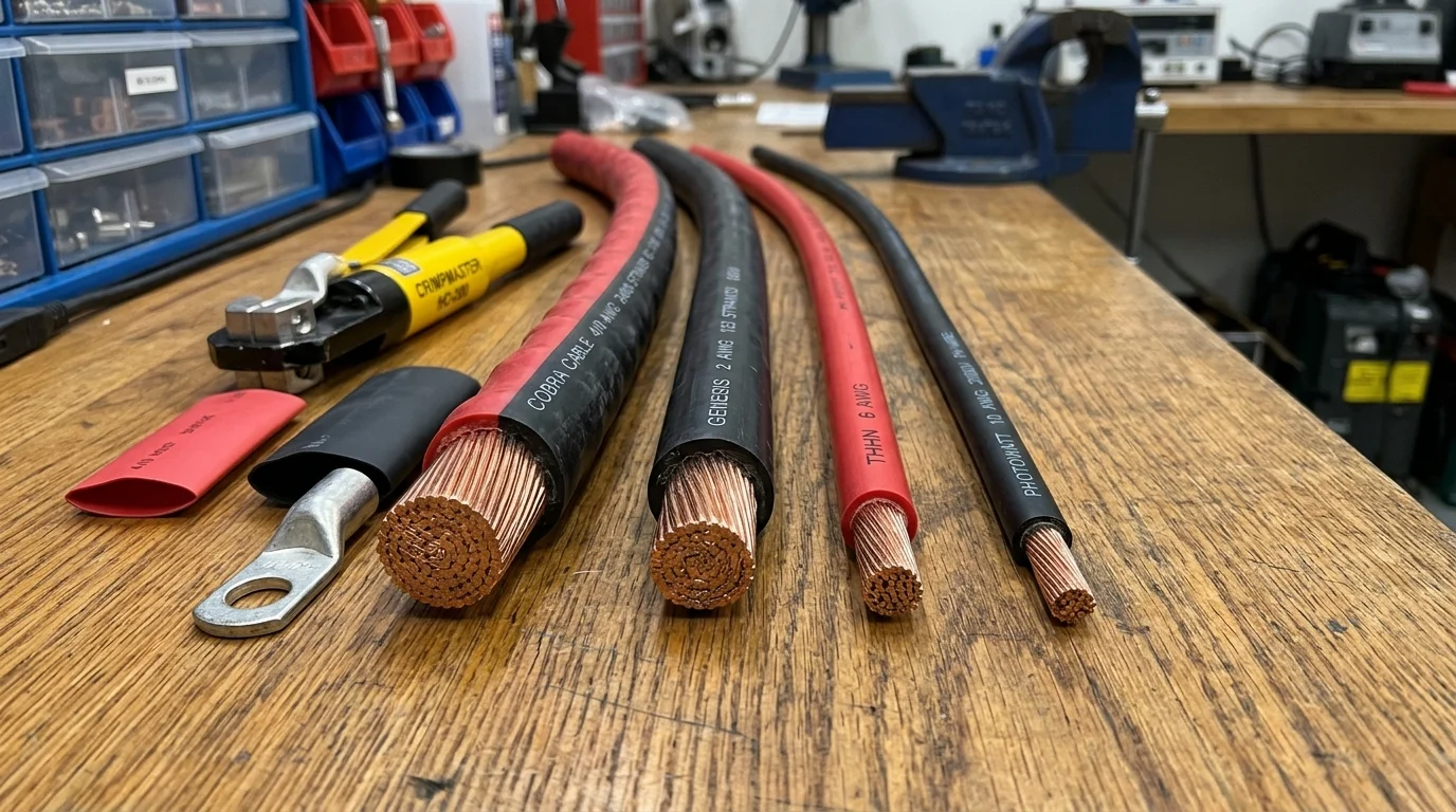
BougeRV 10 AWG Solar Cable (50ft / 100ft Spool)
Features genuine tinned copper stranding to prevent marine and outdoor atmospheric oxidation. Double-layer XLPE insulation withstands extreme UV, moisture, and temperatures from -40°F to +194°F (-40°C to +90°C).
Check Current Cable Pricing →
2. Heavy-Duty Hydraulic Cable Lug Crimper: TEMCo Industrial Hydraulic Crimper
TEMCo Industrial 16-Ton Hydraulic Cable Crimper
Delivers 16 tons of hydraulic compression to create gas-tight, cold-welded electrical connections between heavy battery cables and terminal ring lugs. Eliminates resistive crimp failures that trigger inverter shutdowns.
View Professional Crimper Kit →
Interactive Sizing and Runtime Calculators
Test your solar and battery circuits using our suite of interactive engineering tools:
- Solar Generator Runtime Calculator: Calculate true usable runtime after accounting for system voltage drop and inverter tare loss.
- Solar Cold Temperature Voltage Calculator: Calculate open-circuit voltage expansion on sub-freezing mornings to protect charge controllers.
- Inverter Tare Loss Calculator: Measure 24-hour vampire battery draw on off-grid inverters.
Frequently Asked Questions (FAQ)
Can I use regular extension cords to wire my solar panels?
No. Standard household extension cords use thin 14 AWG or 16 AWG conductors wrapped in low-grade PVC insulation. They are not rated for continuous direct current (DC), will degrade rapidly under outdoor ultraviolet (UV) radiation, and cannot withstand the 300V to 600V DC operating voltages of modern solar strings. Always use certified UL 4703 PV Wire.
Why is 10 AWG the most popular size for solar panels?
Standard solar panel MC4 connectors and junction boxes are pre-manufactured to crimp onto 10 AWG (6.0 mm²) wire. 10 AWG offers the optimal balance of physical flexibility, ampacity (up to 40 Amps at 90°C), and low resistance for typical 10A to 15A solar panel strings over 50-to-100 foot conduit runs.
How do I calculate round-trip distance for voltage drop?
Measure the physical one-way distance in feet between your power source (solar panels or battery) and destination (charge controller or inverter), then multiply by 2. A battery that sits 5 feet away from an inverter requires a 5-foot positive cable and a 5-foot negative cable, creating a 10-foot round-trip electrical path.
Why does tinned copper cost more than bare copper?
Tinned copper wire features individual copper strands electroplated with a microscopic layer of tin. While bare copper oxidizes into green copper carbonate when exposed to humidity or marine salt air, tin resists chemical oxidation indefinitely. Tinned copper ensures connection resistance remains near zero for decades.