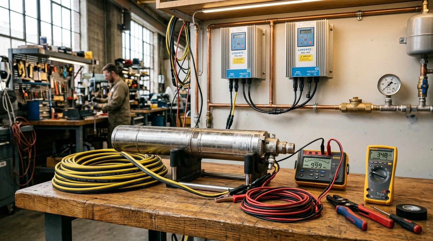
Executive Summary: The Physics of Downhole Circuit Resistance and Pump Failure
Deep-well submersible pumps represent the lifeblood of off-grid homesteads, livestock pastures, and agricultural irrigation operations. Powered by dedicated solar arrays through variable frequency drives (VFDs) or hybrid inverters, these submerged machines lift water from depths between one hundred and over one thousand feet.
Yet, despite investing in high-efficiency solar panels and premium pumps, system installers frequently encounter baffling downhole failures:
- Pumps that run smoothly on surface test tanks stall immediately when lowered into deep casings.
- Inverters repeatedly trip on instantaneous over-current or locked-rotor alarms during midday starting attempts.
- Submersible motor windings overheat and short to ground within months of commissioning, despite drawing running currents well below nameplate limits.
Almost universally, these catastrophic failures originate from a single overlooked electrical engineering factor: downhole conductor resistance and dynamic starting voltage drop.
Unlike surface appliances situated a few feet from an electrical panel, a deep-well pump motor operates at the end of an extreme transmission circuit. The current must travel from the surface solar array through the controller, traverse the wellhead casing, descend hundreds of feet through continuous hydrostatic water pressure, and return. If the drop cable is undersized by even one standard wire gauge, the voltage collapse during motor acceleration chokes starting torque, locking the rotor in place and converting electrical potential into destructive internal heat.
Electrical Anatomy of Submersible Solar Well Pumps
Single-Phase Two-Wire Versus Three-Wire Induction Motors
Traditional deep-well water systems rely on single-phase alternating current (AC) split-phase induction motors (Franklin Electric, Grundfos, or Goulds architectures). These motors are divided into two fundamental configurations:
-
Two-Wire Submersible Motors:
- Incorporate only two power conductors plus an equipment grounding conductor down the borehole.
- The auxiliary start winding, centrifugal switch, or solid-state electronic triac switch and start capacitor are hermetically sealed inside the submersible motor housing at the bottom of the well.
- Failure Hazard: When downhole voltage drops during startup, the internal switch may fail to disconnect the start winding in time, incinerating the internal start capacitor and requiring a crane or pump pull rig to replace the entire submerged unit.
-
Three-Wire Submersible Motors:
- Utilize three power conductors (typically color-coded Black, Red, Yellow) plus a bare or green ground wire.
- The start capacitor, run capacitor, and heavy magnetic potential relay are housed safely on the surface inside a Surface Control Box.
- Engineering Advantage: The surface control box isolates sensitive starting components where they can be tested, adjusted, and serviced without pulling hundreds of feet of wet drop pipe. Furthermore, surface monitoring allows precise diagnosis of winding resistance and thermal overload trips.
+-----------------------------------------------------------------------------+
|               SUBMERSIBLE MOTOR TOPOLOGY ARCHITECTURE                       |
+-----------------------------------------------------------------------------+
 Surface Enclosure                                Downhole Well Motor
┌───────────────────────────┐                    ┌────────────────────────────┐
│ THREE-WIRE CONTROL BOX    │─── Black (Main) ──►│ Main Run Winding           │
│ Start Cap, Run Cap, Relay │─── Red (Start) ───►│ Auxiliary Start Winding    │
│ Thermal Overload Breaker  │─── Yellow (Common)►│ Common Neutral Return      │
└───────────────────────────┘─── Green (Ground) ─►│ Motor Chassis Ground       │
                                                 └────────────────────────────┘
Permanent Magnet Brushless Direct Current Submersible Motors
Modern solar-optimized submersible pumps (such as SunPumps, Lorentz, and RPS Pro Series) bypass AC induction limitations entirely by deploying Permanent Magnet Brushless DC (BLDC) or synchronous permanent magnet motors.
Rather than relying on high magnetizing currents to induce a rotor field, BLDC motors utilize high-grade Neodymium permanent magnets. The surface VFD electronic controller commutates the three-phase stator windings electronically based on Hall sensor telemetry or back-electromotive force (back-EMF) sensing.
- Superior Starting Torque: BLDC motors achieve full rated starting torque at near-zero RPM without drawing enormous locked-rotor current spikes.
- High-Voltage DC Operation: Solar pumping controllers frequently boost array voltage up to three hundred or four hundred volts DC, slashing current draw () and enabling significantly smaller downhole copper conductors over extreme depths.
The Mathematics of Conductor Resistance and Downhole Voltage Drop
Copper Resistivity and Temperature Derating in Deep Wells
Conductor electrical resistance () is determined by material resistivity (), conductor cross-sectional area (), and total one-way circuit length ():
For standard stranded uncoated annealed copper conductors at twenty degrees Celsius, resistivity is approximately:
However, deep boreholes exhibit varying thermal environments. While groundwater at the bottom of a four-hundred-foot well may sit at a cool twelve degrees Celsius, the drop cable running from the solar array across the ground surface, through metal conduit on sun-baked pads, and down the dry upper casing easily experiences temperatures exceeding fifty degrees Celsius.
Conductor resistance increases linearly with temperature according to the temperature coefficient of copper ():
Failing to account for high-temperature surface conduit sections underestimates loop resistance by eight to twelve percent.
Circuit Loop Distance Calculations for Submerged Applications
In standard National Electrical Code branch circuit calculations, distance is measured from the panel to the load. In a submersible solar well installation, the total one-way circuit length () is the sum of two distinct segments:
Where:
- represents the linear distance from the solar inverter or pump controller enclosure to the wellhead casing cap.
- represents the depth from the wellhead down to the submersible motor terminals.
For single-phase two-wire or DC circuits, the electrical current traverses this distance twice (outbound and return), creating a total conductive loop of . The total voltage drop () under operating current () is:
Percentage voltage drop is given by:
For critical submersible applications, the running voltage drop must not exceed five percent, and under high-ambient agricultural conditions, should be engineered to under three percent.
Motor Starting Dynamics: Locked Rotor Amperes and Torque Collapse
Starting Torque Dependence on Operating Terminal Voltage
The most dangerous pitfall in well pump wiring is sizing the cable based solely on continuous running full-load amperes (FLA).
When an induction motor is stationary (), there is zero back-electromotive force to oppose current flow. The motor behaves as a short-circuited transformer, drawing Locked Rotor Amperes (LRA)—typically five to seven times higher than running FLA:
For a typical two-horsepower two-hundred-thirty-volt single-phase pump motor:
- Running Current ():
- Locked Rotor Starting Current ():
The fundamental mechanical torque () generated by an AC induction motor rotor is proportional to the square of the terminal voltage ():
This squared relationship creates an aggressive cliff for motor starting capability:
| Terminal Voltage Ratio | Percentage Nominal Voltage | Available Starting Torque () | Impact on Submersible Pump |
|---|---|---|---|
| 100% | 100.0% | Normal instantaneous acceleration (under 0.3s) | |
| 95% | 90.2% | Reliable start under moderate hydraulic head | |
| 90% | 81.0% | Sluggish start; high inrush duration | |
| 85% | 72.2% | Severe risk of stall against static head pressure | |
| 80% | 64.0% | Complete motor lock; thermal overload trip |
If drop cable resistance drops terminal voltage by fifteen percent during starting inrush, available starting torque collapses by twenty-eight percent. If the pump is lifting water against five hundred feet of static water column with check valves holding back immense head pressure, the motor simply cannot turn.
Stall Current Thermal Overload and Winding Insulation Breakdown
When starting torque is insufficient to overcome static head and impellers remain locked, the motor draws sixty-eight amperes through its fine downhole stator windings. Because heat generation scales with the square of current (), the motor generates twenty-five to forty-nine times more heat per second than during normal operation!
Submersible motors depend entirely on the convective cooling of water rushing past the motor sleeve into the pump intake. When stalled, water flow is zero. Within four to six seconds, downhole winding temperatures spike past one hundred eighty degrees Celsius, melting Class B or Class F varnish insulation and causing an unrecoverable ground fault.
Submersible Cable Selection and Environmental Durability
Flat Jacketed Versus Twisted Conductor Geometries
Submersible pump cable is specially manufactured to survive continuous immersion in harsh mineralized groundwater under hydrostatic pressures exceeding hundreds of pounds per square inch:
-
Flat Jacketed Submersible Cable (Type THW / PVC / Neoprene):
- Conductors lie parallel inside an extruded outer protective web.
- Advantages: Low profile allows smooth clearance between pump motor and inside diameter of narrow four-inch or six-inch steel casing. Easy to secure against drop pipe with sanitary cable guard clips.
- Limitations: Parallel conductors experience higher mutual capacitance and electromagnetic radiation when driven by high-frequency VFD PWM waveforms.
-
Twisted Submersible Cable (Twisted Three-Core with Ground):
- Insulated conductors are twisted symmetrically along the cable run.
- Advantages: Symmetrical geometry cancels electromagnetic interference, balances line inductance, and provides superior mechanical flexibility during deep hoist operations. Highly recommended when installing modern variable speed drives.

Insulation Degradation Under Hydrostatic Pressure and Minerals
Standard building wire (such as THHN or Romex) must never be lowered into a water well. Standard THHN insulation features a nylon outer jacket that absorbs moisture over time, softening the PVC dielectric until pinhole electrical leaks develop into the casing water.
True submersible pump drop cable features:
- Cross-Linked Polyethylene (XLPE) or High-Density PVC: Impervious to water absorption even at one thousand feet of hydrostatic head pressure ().
- Heavy Abrasion-Resistant Jacket: Resists sharp burrs on casing welds as torque twist rotates the pipe during pump starting and stopping cycles.
Downhole Splicing Techniques and Hydrostatic Sealing Standards
Dual-Wall Heat-Shrink Splices with Thermoplastic Adhesive
The electrical connection between the pump motor lead pigtail and the long drop cable must remain one hundred percent waterproof indefinitely. A single microscopic void allows high-voltage AC or DC potential to bridge into surrounding well water, creating an immediate ground fault that trips solar inverters.
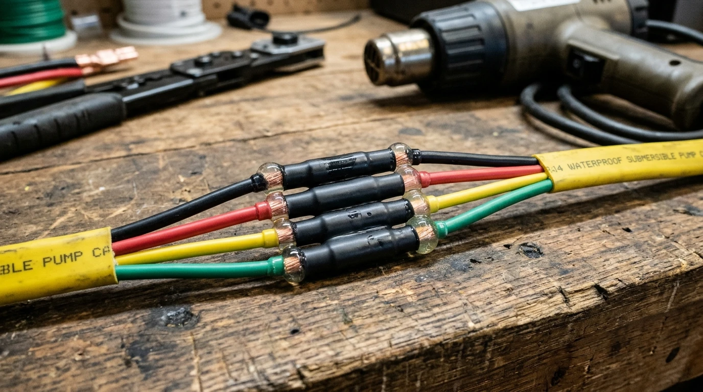
The gold-standard downhole splicing method employs Dual-Wall Adhesive-Lined Heat-Shrink Tubing:
- Conductor Prep: Strip conductors with calibrated strippers, avoiding nicking fine copper strands.
- Staggered Crimp Connections: Stagger the splices along the cable length by two inches so all butt connectors do not sit adjacent to each other, preventing an oversized lump that catches on casing collars.
- Seamless Copper Butt Connectors: Use heavy seamless copper butt splices crimped with a calibrated ratcheting crimp tool. Never use automotive uninsulated crimpers that punch holes in the metal barrel.
- Adhesive Flow Verification: Slip individual dual-wall polyolefin heat-shrink sleeves over each conductor. Apply heat evenly with an electric heat gun until the internal thermoplastic adhesive melts, bubbling out as a glossy, uniform thirty-six-degree donut seal around both ends of the sleeve.
- Outer Armor Wrap: Apply a heavy master outer heat-shrink sleeve across the entire four-conductor assembly, sealing the jacket against abrasive mechanical friction.
Epoxy Resin Cast Kits for Deep High-Pressure Boreholes
For extreme deep-well applications exceeding six hundred feet (where hydrostatic pressures surpass two hundred fifty pounds per square inch), field engineers recommend Cast Epoxy Resin Splice Kits (such as 3M Scotchcast).
The crimped splice is suspended inside a rigid plastic snap-together mold. Two-part polyurethane or epoxy resin is mixed and poured into the chamber, encasing the bare metal junctions in a solid, void-free rock-hard block that withstands extreme chemical exposure and hydrostatic crush forces.
Comparison: Submersible Drop Cable Sizing and Voltage Drop Limits
The following engineering reference table details maximum recommended one-way circuit lengths (in feet) for two-hundred-thirty-volt single-phase solar submersible pumps to maintain under five percent running voltage drop at full load:
| Motor Rating | Running FLA | Locked Rotor LRA | 12 AWG Copper | 10 AWG Copper | 8 AWG Copper | 6 AWG Copper | 4 AWG Copper |
|---|---|---|---|---|---|---|---|
| 0.50 HP | 4.6 A | 24.0 A | 380 ft | 600 ft | 950 ft | 1,480 ft | 2,340 ft |
| 0.75 HP | 6.2 A | 32.0 A | 280 ft | 450 ft | 710 ft | 1,110 ft | 1,760 ft |
| 1.00 HP | 8.2 A | 42.0 A | 210 ft | 340 ft | 540 ft | 840 ft | 1,330 ft |
| 1.50 HP | 10.6 A | 54.0 A | 160 ft | 260 ft | 420 ft | 650 ft | 1,030 ft |
| 2.00 HP | 12.8 A | 68.0 A | 130 ft | 210 ft | 340 ft | 530 ft | 840 ft |
| 3.00 HP | 17.0 A | 88.0 A | 100 ft | 160 ft | 260 ft | 400 ft | 630 ft |
| 5.00 HP | 27.5 A | 142.0 A | Not Permitted | 100 ft | 160 ft | 250 ft | 390 ft |
Variable Frequency Drive Reflected Wave Spikes and Output Filtering
When driving submersible pumps with modern solar Variable Frequency Drives (VFDs), the drive converts solar DC into pulsed AC using high-speed Insulated Gate Bipolar Transistors (IGBTs) switching at four to sixteen kilohertz.
These rapid switching pulses feature extremely steep voltage rise times ( exceeding ten thousand volts per microsecond). When these high-frequency voltage pulses travel down hundreds of feet of drop cable, the impedance mismatch between the cable and the motor winding causes voltage wave reflection:
- The reflected wave adds in phase to the incoming pulse, doubling the peak voltage seen at the motor terminals.
- On a two-hundred-thirty-volt VFD system, peak downhole voltage spikes can easily exceed one thousand two hundred volts!
- Over time, these repetitive microsecond spikes punch pinhole corona discharge channels through the motor winding enamel, destroying the pump.
Engineering Mitigations for Long-Lead VFD Installations:
- Reduce VFD Carrier Frequency: Lower the PWM switching carrier frequency from twelve kilohertz down to two or four kilohertz, substantially softening voltage gradients.
- Install an Output Load Reactor: Place a three percent or five percent line reactor at the wellhead between the VFD and the drop cable. The inductor filters sharp pulse edges and suppresses high-frequency reflections.
- Deploy dV/dt Filters: For cable runs exceeding five hundred feet, install a dedicated LC low-pass filter to clamp voltage spikes below one thousand volts peak, guaranteeing motor winding longevity.
Comprehensive Solar Well Pump Cable Sizing and Commissioning Checklist
- Total Conductor Loop Distance Sizing: Sum the surface horizontal trench length and the downhole pump hanging depth to establish the true total one-way circuit length.
- Voltage Drop Sizing Verification: Verify that selected copper wire gauge maintains running voltage drop strictly under five percent (preferably under three percent for deep agricultural installations).
- Locked-Rotor Torque Margin Check: Calculate instantaneous starting voltage drop at five times full-load current; verify that terminal starting voltage does not fall below eighty-five percent of nominal nameplate rating.
- Insulation Resistance Megohmmeter Audit: Before dropping the pump into the borehole, submerge motor and splice in a clean water barrel; test conductor-to-water insulation with a five-hundred-volt megohmmeter (reading must exceed twenty megohms).
- Submersible Splice Integrity Check: Inspect dual-wall heat-shrink tubing to confirm hot-melt adhesive has extruded uniformly from both ends, forming a permanent thirty-six-degree hermetic seal.
- Mechanical Cable Fastening: Secure drop cable to the poly or steel drop pipe every ten to fifteen feet using UV-resistant submersible cable ties or stainless steel banding clips with protective rubber pads to prevent chafe against well casing.
- VFD Load Reactor Integration: If drop cable length exceeds three hundred feet on a high-frequency PWM inverter or VFD, install an output reactor or filter at the wellhead to suppress destructive reflected wave spikes.