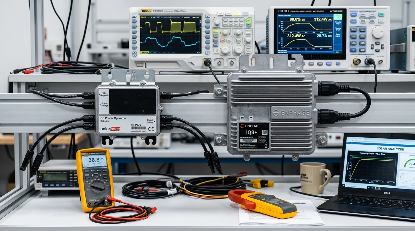
Executive Summary: The Evolution of Module-Level Power Electronics
In traditional residential and commercial photovoltaic design, solar modules are wired in series strings, much like old-fashioned holiday lights. While cost-effective and mechanically simple, series stringing imposes an unavoidable physical compromise: every solar panel in the string must conduct the exact same electrical current. If chimney shade, an overhead power line, tree branches, or heavy bird droppings obscure a single cell, the output of the entire ten-to-fifteen-panel string collapses.
To conquer this fundamental limitation, photovoltaic engineering developed Module-Level Power Electronics (MLPE). By placing intelligent power conversion hardware directly beneath each solar panel on the roof, system designers can optimize, monitor, and regulate the electrical behavior of every module independently.
Today, the MLPE market is dominated by two competing architectural philosophies:
- DC Power Optimizers (e.g., SolarEdge, Tigo Energy): Specialized DC-to-DC converters mounted at each module that dynamically condition voltage and current, feeding an optimized high-voltage DC bus to a single, high-efficiency ground-level central inverter.
- Distributed Microinverters (e.g., Enphase Energy, Hoymiles): Miniature, fully autonomous grid-interactive inverters mounted at each module that convert DC power directly into standard alternating current (such as 120V/240V split-phase) right at the panel racking rail.
Both architectures successfully eliminate string mismatch, maximize energy harvest on complex roofs, and provide native compliance with the National Electrical Code (NEC 690.12) rapid shutdown requirements. However, their underlying electrical physics, thermal operating environments, lifetime reliability, and maintenance economics differ fundamentally.
The Fundamental Physics of Series String Current Bottlenecks
To understand why MLPE delivers substantial energy gains, one must analyze the electrical behavior of unoptimized series strings under non-uniform illumination.
+-------------------------------------------------------------+
|        UNOPTIMIZED STRING VS MLPE ELECTRICAL CURRENT        |
+-------------------------------------------------------------+
|                                                             |
|   TRADITIONAL STRING (Weakest-Link Bottleneck):             |
|   [Panel 1: 10A] -> [Panel 2: 10A] -> [Panel 3: 3A (SHADED)]|
|                                             |               |
|   Entire Series String Current Throttled to: 3.0 Amperes    |
|   Result: 70% of potential energy lost across unshaded units|
|                                                             |
|   -------------------------------------------------------   |
|                                                             |
|   DC OPTIMIZER STRING (Dynamic Impedance Matching):         |
|   [Panel 1: 10A]    [Panel 2: 10A]    [Panel 3: 3A (SHADED)]|
|         |                 |                 |               |
|   [Optimizer 1]     [Optimizer 2]     [Optimizer 3]         |
|    Buck: 40V @ 10A   Buck: 40V @ 10A   Boost: 12V @ 10A     |
|         |                 |                 |               |
|   Uniform String Bus Current Maintained at: 10.0 Amperes    |
|   Result: Unshaded panels produce 100%; Shaded contributes  |
+-------------------------------------------------------------+
The Weakest Link Phenomenon and Module Mismatch Losses
Kirchhoff’s Current Law dictates that the current flowing through components wired in series must be identical at every point in the circuit:
In an unshaded string under standard test conditions, each module operates at its maximum power current ( to ). When one module is partially shaded, its photogenerated current () drops proportionally to the reduction in photon flux.
Because the shaded module cannot conduct the higher current demanded by the rest of the string, it acts as a high-resistance bottleneck. The central inverter’s Maximum Power Point Tracker (MPPT) faces a lose-lose dilemma:
- Force the string current down to match the shaded panel’s low output, sacrificing fifty to seventy percent of the unshaded panels’ generation.
- Pull full current through the string, forcing the shaded panel into reverse bias and activating its internal bypass diodes.
Limitations of Passive Bypass Diodes Under Dynamic Shade
Standard silicon solar modules incorporate three internal bypass diodes wired across sub-strings of twenty to twenty-four cells. When a sub-string is heavily shaded, the bypass diode becomes forward-biased, routing string current around the dead cells.
While bypass diodes prevent catastrophic hot-spot destruction, they are crude, binary mechanisms:
- Voltage Truncation: Activating a bypass diode eliminates one-third of the panel’s voltage (a loss of twelve to fifteen volts).
- Conduction Heat Losses: Standard P-N or Schottky diodes possess a forward voltage drop ( to ). Conducting full string current generates substantial continuous heat inside the module junction box ( to ), elevating localized cell temperatures and accelerating encapsulant browning.
- Inverter MPPT Hunting Failures: In partially shaded strings, the Power-Voltage (P-V) curve develops multiple local peaks. Conventional string inverters frequently become trapped in local sub-optimal power peaks, failing to locate the true global maximum power point.
Architecture of Direct Current Power Optimizers
DC power optimizers resolve the string bottleneck by decoupling individual module operating voltages from the overall series string current.
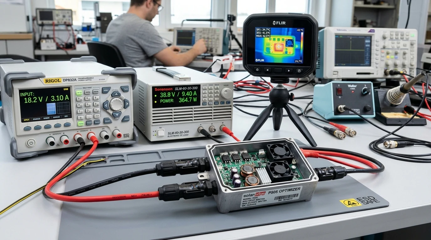
Buck-Boost Conversion and Dynamic Impedance Matching
A DC power optimizer contains an internal high-efficiency switch-mode DC-to-DC converter operating at hundreds of kilohertz, controlled by a dedicated digital microprocessor.
The optimizer executes localized MPPT on its specific panel, continuously calculating the module’s true maximum power:
Through high-speed Pulse Width Modulation (PWM) across internal power MOSFETs, the optimizer transforms the power into whatever voltage and current combination is necessary to match the series string current:
Where:
- is the DC-to-DC conversion efficiency (typically to ),
- is the common current flowing through the series circuit.
The Buck-Boost Mechanics in Practice
Suppose a series string operates at a current of :
- Unshaded Module: Producing (). The optimizer passes power straight through with near-zero transformation (, ).
- Shaded Module: Producing only due to tree coverage (). Rather than dragging the string down to , the optimizer steps voltage down and boosts current:
The shaded module contributes its full remaining one hundred and twenty watts into the string at , while allowing every unshaded module in the string to continue pumping full current unrestricted.
Central Inverter Interfacing and Fixed String Voltage Rails
In optimized architectures like SolarEdge, the relationship between the optimizers and the central inverter is cooperative.
Traditional inverters must accommodate wide string voltage variations (from two hundred to six hundred volts) as sunlight and ambient temperatures fluctuate throughout the day. In contrast, SolarEdge optimizers communicate with the central inverter via powerline carrier (PLC) telemetry, dynamically coordinating output voltages to maintain a strictly fixed high-voltage DC bus (typically for single-phase residential inverters or to for commercial three-phase systems).
Because the central inverter operates with a constant, known DC input rail, its internal inversion bridge functions at maximum efficiency (up to ninety-nine percent), significantly reducing inverter size, weight, and internal heat generation.
Architecture of Distributed Microinverters
Distributed microinverters bypass high-voltage DC architecture altogether. Instead of optimizing DC current for a central inverter downstream, a microinverter is a self-contained, utility-interactive power station attached directly to the racking beneath each module.
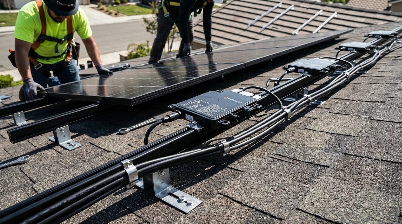
Individual Maximum Power Point Tracking and Alternating Current Conversion
A modern microinverter (such as an Enphase IQ8) takes low-voltage DC directly from a single solar module ( to DC) and converts it immediately into clean, synchronized alternating current ( split-phase AC at sixty hertz).
Each microinverter operates with complete independence:
- It possesses its own dedicated MPPT microcontroller and control firmware.
- It tracks the exact maximum power point of its paired panel with zero interaction or reliance on neighboring units.
- Its AC output connects in parallel onto a common rooftop AC trunk cable (e.g., Enphase Q-Cable), exactly like parallel branch circuits in residential household wiring.
Because microinverters connect in parallel:
If a tree completely obscures two panels on a twelve-module roof, those two microinverters produce zero watts while the remaining ten microinverters generate maximum rated AC power into the branch circuit. There is zero string bottleneck, zero voltage compromise, and zero cross-module interference.
Elimination of High-Voltage Direct Current Roof Circuits
From a fire and electrical safety perspective, microinverters introduce a profound architectural shift: the complete elimination of high-voltage DC on the roof.
In traditional string and DC optimizer installations, series strings carry up to six hundred volts DC (residential) or one thousand to fifteen hundred volts DC (commercial). Direct current does not possess natural zero-crossings, making DC arcs notoriously difficult to extinguish once ignited. A compromised MC4 connector or rodent-chewed conductor can sustain a three-thousand-degree plasma arc, presenting a severe rooftop fire risk.
With microinverters:
- DC wiring is confined to the six-inch factory leads between the panel junction box and the microinverter casing.
- The conductors leaving the microinverter are standard alternating current, which naturally crosses zero voltage one hundred and twenty times per second, extinguishing arcs before plasma can ignite building materials.
- Compliance with NEC 690.12 Rapid Shutdown is inherently complete at the hardware level: de-energizing the main AC breaker shuts down all microinverters instantly, collapsing rooftop voltage to zero in milliseconds.
Energy Harvesting Performance: Partial Shading and Complex Azimuths
When selecting between DC optimizers and microinverters, engineers must quantify real-world energy recovery across challenging roof geometry.
+--------------------------------------------------------------+
|            SHADING MITIGATION AND HARVEST DYNAMICS           |
+--------------------------------------------------------------+
|                                                              |
|   Scenario A: Single Roof Plane, Zero Shading                |
|   - Traditional String Inverter:  100% Benchmark             |
|   - DC Power Optimizers:          100.5% (Eliminates mismatch|
|   - Distributed Microinverters:   99.5% (Slightly lower peak |
|                                          inversion efficiency|
|                                                              |
|   Scenario B: Multi-Azimuth Hip/Valley Roof (East-West Split)|
|   - Traditional String Inverter:  72% - 82% (Severe mismatch)|
|   - DC Power Optimizers:          96% - 98% (Recovers energy)|
|   - Distributed Microinverters:   97% - 99% (Complete freedom|
|                                                              |
|   Scenario C: Heavy Dynamic Tree / Chimney Shading           |
|   - Traditional String Inverter:  45% - 65% (String collapse)|
|   - DC Power Optimizers:          80% - 88% (String active)  |
|   - Distributed Microinverters:   84% - 92% (Complete        |
|                                              module isolation|
+--------------------------------------------------------------+
Multi-Oriented Roof Planes and Hip-and-Valley Layouts
Modern suburban architecture frequently features complex roof geometry: hip roofs, gables, dormers, and varying pitch angles facing East, South, and West.
On an unoptimized string inverter, modules facing East cannot be wired into the same MPPT string as modules facing South; doing so causes catastrophic current mismatch that destroys energy yield. Even dual-MPPT inverters struggle when a home has four or five distinct roof facets that can only accommodate three to four panels each.
Both DC optimizers and microinverters excel on complex roofs, but with distinct constraints:
- Microinverters: Offer complete modular freedom. An installer can place two panels on an East dormer, four on a South face, and three on a West slope. Because each microinverter operates autonomously on an AC branch, array layout is completely unrestricted by minimum string lengths.
- DC Optimizers: Offer exceptional flexibility, but remain bound by minimum string length and voltage requirements. In a SolarEdge single-phase system, a string must contain a minimum number of optimizers (typically eight to ten standard units) to ensure the cumulative output voltage can satisfy the fixed three-hundred-and-eighty-volt DC bus rail.
Soiling and Snow Melting Recovery Benchmarks
On agricultural sites with heavy dust, pollen accumulation, or winter snow cover, panels soil unevenly. Lower rows accumulate heavy sediment or snow drifts while upper rows clear rapidly in morning sun.
Under partial snow coverage, microinverters demonstrate a minor performance advantage. As top panels clear, their microinverters begin producing full power immediately, generating localized heat that accelerates snow melting across adjacent modules. In DC optimizer strings, if too many modules in a string are buried under thick snow, the string may struggle to achieve the threshold voltage needed to wake the central inverter, delaying generation by several hours.
Comprehensive Engineering Comparison: Optimizers Versus Microinverters
While energy production metrics often favor microinverters on challenging roofs, total cost of ownership is governed by hardware reliability, warranty structures, and replacement logistics.
| Engineering Factor | Traditional String Inverter | DC Power Optimizers + Central Inverter | Distributed Microinverters |
|---|---|---|---|
| Rooftop Electronics Density | Zero (Pure passive panels) | Moderate (One converter per module) | High (Full inverter per module) |
| Operating Temperature Environment | Controlled (Garage / Shaded wall) | Severe (40°C - 75°C under roof deck) | Severe (40°C - 75°C under roof deck) |
| Mean Time Between Failures (MTBF) | High (Single central failure point) | Moderate (Multiple roof components) | High per unit (Over 1M hours MTBF) |
| Standard Hardware Warranty | 10 to 12 Years | 25 Years (Optimizers) / 12 Yrs (Inverter) | 25 Years (Complete System) |
| Failure Mode Impact | Total System Outage (100% loss) | Total System Outage if Inverter Fails | Single Module Loss (5-8% outage) |
| Replacement Labor Complexity | Low (Ground-level wall swap, 1 hr) | Mixed (Inverter easy; Optimizer hard) | High (Requires roof truck & panel pull) |
| Battery Storage Interfacing | AC-Coupled or DC Hybrid | Native DC-Coupled High Efficiency | Requires AC-Coupling Conversion |
| Installed System Cost | Lowest ($) | Moderate ($$) | Highest ($$$) |
Long-Term Reliability, Heat Dissipation, and Maintenance Economics
The ultimate battleground between DC optimizers and microinverters centers on where the sensitive power conversion components reside physically.
Rooftop Ambient Thermal Stress and Component Failure Rates
A solar panel heats up significantly under intense summer radiation, routinely operating at twenty to thirty-five degrees Celsius above ambient air. On a ninety-five-degree-Fahrenheit afternoon, the confined airspace between the backsheet and the roof deck transforms into a thermal oven, reaching temperatures between sixty and seventy-five degrees Celsius ().
Power electronics loathe heat:
- Microinverters: Contain complex power conversion circuitry: electrolytic smoothing capacitors, toroidal high-frequency transformers, planar power inductors, and full bridge inversion MOSFETs. To survive twenty-five years in this brutal thermal environment, top manufacturers (like Enphase) utilize hermetically potted cast-aluminum enclosures and specialized semiconductor designs that completely eliminate failure-prone wet electrolytic capacitors.
- DC Optimizers: Contain substantially fewer components than a full inverter, functioning primarily as a DC-to-DC buck-boost stage with solid-state ceramic capacitors and potted inductors. Their simpler internal Bill of Materials (BOM) naturally yields higher theoretical MTBF under high heat.
Replacement Logistics: Ground-Level Inverter Swap Versus Roof Servicing
The critical economic difference emerges when a component inevitably fails ten to fifteen years into the system’s operational life:
+--------------------------------------------------------------+
|            SERVICEABILITY AND MAINTENANCE LOGISTICS          |
+--------------------------------------------------------------+
|                                                              |
|   DC OPTIMIZER SCENARIO:                                     |
|   Central Inverter Fails at Year 12:                         |
|   - Technician arrives with replacement unit in service van. |
|   - Swap executed at ground level in garage / side wall.     |
|   - Service Time: 45 to 60 Minutes.                          |
|   - Labor Cost: Minimal ($150 - $300). Roof untouched.       |
|                                                              |
|   MICROINVERTER SCENARIO:                                    |
|   Microinverter Fails on Second-Story Steep Roof:            |
|   - Two-person crew required with safety harnesses/ladders.  |
|   - Must unbolt module clamps, lift heavy 45lb panel.        |
|   - Disconnect Q-cable, unbolt microinverter, install new.   |
|   - Re-torque mid-clamps and verify grounding bond.          |
|   - Service Time: 2 to 3 Hours.                              |
|   - Labor Cost: Substantial ($400 - $800 in truck rolls).    |
|   - NOTE: System continues producing 95% power while broken. |
+--------------------------------------------------------------+
With microinverters, a single unit failure is an annoyance rather than an emergency. If one microinverter fails on a twenty-panel system, the remaining nineteen panels continue operating at full capacity. The homeowner can comfortably postpone repairs until routine maintenance or net metering true-up cycles.
With a DC optimizer system, if the central inverter fails, the entire system is down until the wall-mounted unit is serviced. However, performing that replacement requires zero roof work, zero broken roof tiles, and zero hazardous ladder operations.
Engineering Decision Matrix: Sizing Optimizers Versus Microinverters
To select the definitive MLPE architecture for any residential or commercial project, engineers should utilize this decision matrix:
[ ] CHOOSE DISTRIBUTED MICROINVERTERS IF:
    - The roof features complex, multi-azimuth geometry with 4+ small facets.
    - Extreme dynamic shading exists from nearby trees, chimneys, or parapets.
    - Eliminating high-voltage DC circuits on the roof is a primary safety mandate.
    - The system owner demands a full 25-year manufacturer warranty across all hardware.
    - Future expansion is planned (adding 2 to 4 modules later is completely trivial).
    - The installation is in a remote area where ground-level inverter swap parts are scarce.

[ ] CHOOSE DC POWER OPTIMIZERS IF:
    - The system incorporates a large DC-coupled battery bank (e.g., SolarEdge Home,
      Tesla Powerwall 3, or Sol-Ark with Tigo) to eliminate DC-AC-DC double conversion.
    - The roof consists of large, uniform planes with moderate or localized shading.
    - Initial upfront hardware budget is a primary engineering constraint.
    - The property owner prefers ground-level serviceability for major power components.
    - Long continuous string runs are required to minimize conduit penetrations.
    - Commercial three-phase 480V service is present (2-to-1 optimizer density economics).
By matching module-level conversion physics to roof geometry, shading profiles, and battery storage topology, solar professionals ensure maximum kilowatt-hour generation, robust safety compliance, and decades of reliable, optimized clean energy production.