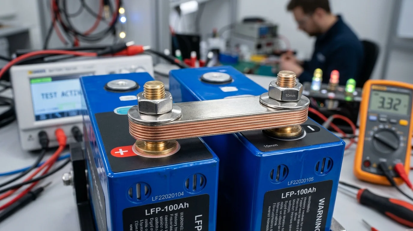
When building a high-capacity 48V DIY lithium iron phosphate (LiFePO4) battery bank, most builders invest obsessively in Grade A prismatic cells and high-end BMS telemetry. Yet, the components that most frequently trigger catastrophic thermal runaway, cell voltage imbalances, and melted terminal posts are the simplest pieces of metal in the entire system: the cell interconnect busbars.
Connecting 16 large-format prismatic cells—such as EVE 280Ah, 304Ah, or 314Ah units—requires 15 series busbars and 2 main terminal takeoffs.
At continuous discharge currents between 100A and 250A (the standard operating range of modern 5kW to 12kW split-phase inverters), even a minuscule contact resistance of 0.2 milliohms () will dissipate significant heat (). Multiplied across 15 connections, undersized or improperly bolted busbars act as miniature heating elements, baking internal cell seals and causing false BMS low-voltage cutoffs.
In this electrical engineering guide, we examine the physics of DC conductor sizing, compare C110 copper versus 6061-T6 aluminum ampacities, explain galvanic corrosion at the copper-aluminum boundary, and provide verified torque specifications with Belleville conical spring washers.
Never use bare, unplated copper busbars directly against aluminum cell terminals, and never use undersized aluminum stock. For continuous 200A discharge on 280Ah–314Ah LiFePO4 packs, use nickel-plated or tin-plated C110 copper busbars with a minimum cross-sectional area of 60 to 80 mm² (e.g. 20mm x 3mm or 25mm x 3mm). Always secure connections with stainless steel Belleville conical spring washers torqued to 4.5 Nm on M6 studs to maintain constant clamping pressure across thermal cycles.
Check Pure Copper Busbars →
Conductor Cross-Sectional Area and Current Density Calculations
To calculate the required dimensions of a DC busbar, electrical engineers rely on the current density rule (DIN 43671 / ASTM B187 standard for electrical conductors).
For stationary battery enclosures with natural convective airflow, safe current density for pure copper ranges between 1.8 and 2.5 Amperes per square millimeter () for a conservative 30°C temperature rise above ambient.
Sizing Formula for Rectangular Busbars
The cross-sectional area () of a rectangular bar is simply:
Required cross-sectional area based on continuous current () and target current density ():
Example: 200A Continuous Discharge (e.g. 10kW Split-Phase Inverter at 48V)
Assuming a conservative current density of :
Standard commercial busbar cross-sections that satisfy this rating:
- 25mm x 4mm: Cross-section (Current density , ultra-cool run)
- 20mm x 3mm: Cross-section (Current density , acceptable for intermittent 150A, runs warm at 200A)
- 30mm x 3mm: Cross-section (Ideal balance of width and terminal stud clearance)
Material Shootout: C110 Copper vs 6061-T6 Aluminum
Many budget DIY builders look at the price of copper and consider substituting aluminum flat bar from the local hardware store. Below is an engineering comparison demonstrating why aluminum demands drastic upsizing.
| Physical & Electrical Property | C11000 ETP Pure Copper | 6061-T6 Structural Aluminum | 1350-O Electrical Aluminum |
|---|---|---|---|
| Electrical Conductivity (% IACS) | 100.0% – 101.5% | 40.0% – 43.0% | 61.0% – 61.8% |
| Electrical Resistivity at 20°C | |||
| Required Area for Equal Resistance | 1.0x (Baseline) | 2.35x Thicker/Wider | 1.64x Thicker/Wider |
| Coefficient of Thermal Expansion (CTE) | |||
| Thermal Conductivity | 390 W/(m·K) | 167 W/(m·K) | 218 W/(m·K) |
| Mechanical Tensile Strength | 220 – 260 MPa | 310 MPa | 85 MPa |
| Natural Surface Oxide State | Conductive / Semi-conductive | Highly Insulating () | Highly Insulating () |
C110 Electrolytic Tough Pitch Copper
C110 copper is 99.9% pure copper with nominal oxygen content. It delivers maximum volumetric electrical efficiency, allowing compact 20mm to 25mm wide bars to fit comfortably on tight prismatic cell tops without bridging neighboring cell vents or balance wires.
- Minimal thermal expansion mismatch with brass/steel terminal studs
- Superior heat-sink effect draws thermal energy out of cell core
- Readily electro-plated with nickel or tin for permanent passivation
6061-T6 Structural Aluminum
While popular in structural framing, 6061-T6 is an alloy containing magnesium and silicon. Its conductivity is less than half of copper, requiring massive 6mm thick bars that crowd terminal studs. Worse, aluminum instantly forms a micro-thin sapphire-like oxide () that acts as an electrical insulator.
- Requires aggressive wire-brushing and conductive paste (Noalox)
- 40% higher thermal expansion rate causes bolt loosening
- High contact resistance triggers local hot-spot degradation
Contact Resistance and Galvanic Corrosion at the Terminal Boundary
In a LiFePO4 battery pack, current does not simply travel down the length of the busbar—it must cross the mating interface between the battery terminal pad and the busbar face.
If the contact resistance across this interface is even 0.3 milliohms, running 200A through it generates:
Twelve watts of localized heat in a tiny 20mm x 20mm terminal area will raise terminal temperatures past 75°C (167°F), softening internal plastic insulator rings and melting laser weld joints.
The Galvanic Corrosion Threat
Most modern prismatic cells (such as EVE LF280K V3) feature laser-welded aluminum positive terminal pads.
When bare copper is clamped directly to bare aluminum in the presence of ambient humidity, an electrochemical galvanic cell forms. On the Anodic Index table:
- Aluminum Anodic Potential: -0.90V
- Bare Copper Anodic Potential: -0.35V
- Galvanic Voltage Difference: 0.55V (Far exceeding the safe 0.15V maximum threshold for non-corrosive environments).
Electrons flow from the more active aluminum to copper. Aluminum ions pit and convert into white non-conductive aluminum hydroxide chalk.
The insulating chalk layer narrows the metallic contact path. Interface resistance jumps from 20 micro-ohms to over 500 micro-ohms.
High-current charging boils the remaining contact patch. BMS reports false cell delta-V; terminal plastic collar melts.
The Solution: Electro-Tin or Nickel Plating
To permanently prevent galvanic corrosion, quality busbars undergo full electrolytic tin or nickel plating:
- Tin-Plated Copper: Tin has an anodic potential of -0.65V. Clamped against aluminum (-0.90V), the voltage difference drops to 0.25V, which is completely benign in indoor battery enclosures.
- Nickel-Plated Copper: Provides superior abrasion resistance, maintaining low contact resistance across hundreds of torque cycles.
Proper Torque Specifications and Belleville Conical Washers
The single most common mistake among amateur solar installers is using standard hardware store split-ring lock washers or over-torquing terminal studs until the internal laser weld shears off.
The Flaw of Standard Split-Lock Washers
Standard carbon-steel split washers (helical spring washers) flatten out under negligible load. Once flattened, they possess virtually zero spring travel. As cells heat up during heavy charging and cool down at night, the thermal expansion mismatch causes the stainless steel bolt to stretch slightly.
After 50 thermal cycles, the flat washer joint relaxes, contact pressure drops, and electrical resistance spikes.
The Engineering Solution: Belleville Conical Disc Springs (DIN 6796)
Belleville washers are conical disc springs stamped from hardened 304 or 316 stainless steel. When tightened, the cone deflects elastically, storing thousands of Newtons of continuous spring energy.
- Constant Clamping Force: Even if the copper busbar and aluminum terminal expand and contract by 0.05mm, the Belleville washer maintains steady, continuous pressure across the joint.
- Vibration Resistance: Completely eliminates loosening caused by vehicle transit in mobile RV and marine installations.
Correct Terminal Stacking Order (Top to Bottom)
Calibrated Torque Ratings: The Golden Numbers
Prismatic battery terminal studs are welded to thin internal aluminum foil tabs. Over-torquing will permanently twist and shear the internal weld, ruining a $75 to $100 cell instantly.
- M6 Threaded Studs / Blind Holes: 4.0 to 4.5 Nm (35 to 40 inch-pounds). Never exceed 5.0 Nm!
- M8 Threaded Studs / Blind Holes: 6.0 to 7.0 Nm (53 to 62 inch-pounds). Never exceed 8.0 Nm!
Always use an insulated, calibrated 1/4-inch drive torque wrench. Hand-tightening with an Allen key or socket wrench is a guaranteed recipe for terminal failure.
Solid vs Flexible Laminated Copper Busbars
Should you use rigid solid copper bars or flexible laminated busbars?
While solid copper bars are inexpensive and easy to fabricate, they transmit mechanical stress directly between cells. As cells swell and contract during normal cycling, rigid bars pry against terminal studs, risking laser-weld fatigue.
Flexible Laminated Busbars—composed of 10 to 20 ultra-thin (0.1mm to 0.2mm) copper foils welded together only at the terminal ends—offer 2.5mm of axial flex while maintaining identical electrical cross-sectional area. For high-cycle homestead systems, flexible busbars are the superior choice.
Nickel-Plated Flexible Busbars & Belleville Conical Washers
High-purity C110 laminated copper, anti-corrosion nickel plating & DIN 6796 spring washers.