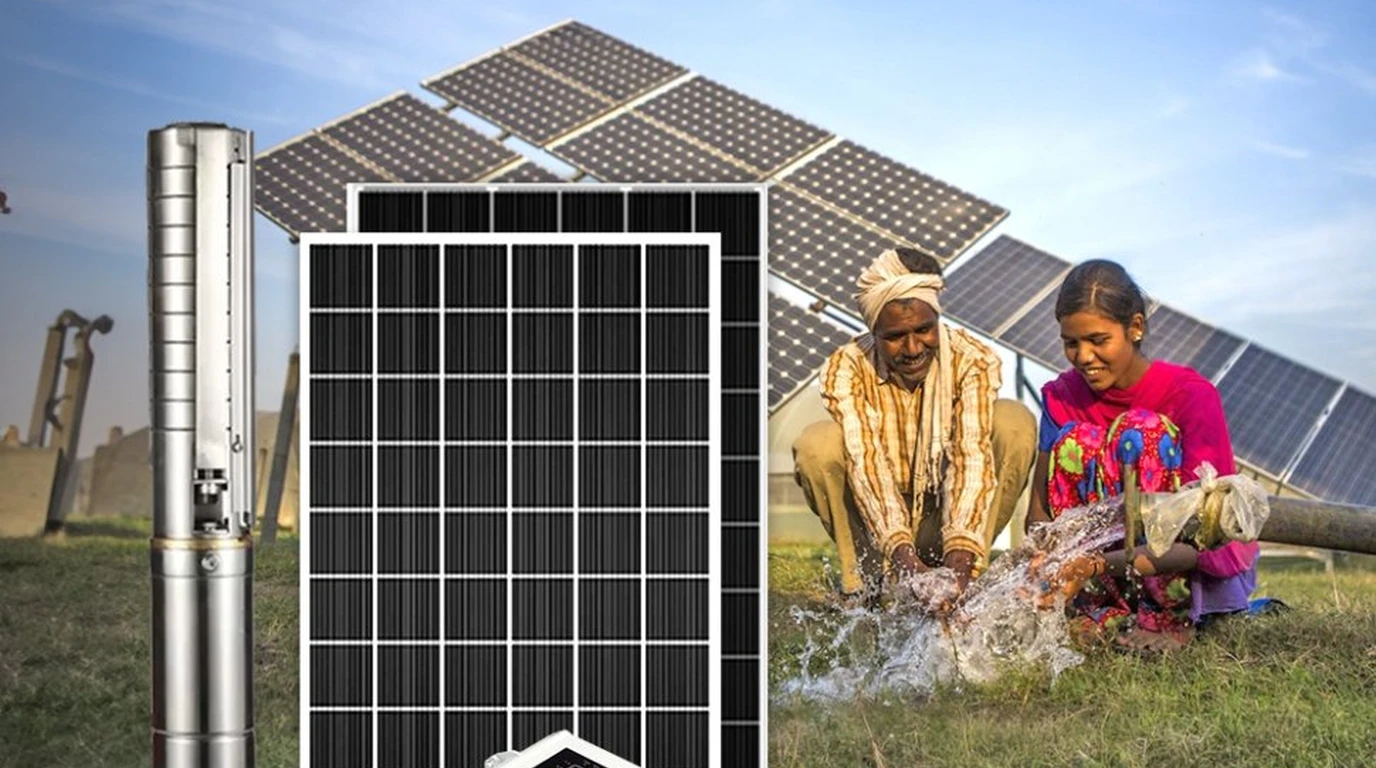
Designing a solar-powered water pumping system for a remote homestead, ranch, or off-grid cabin is fundamentally an exercise in applied fluid dynamics and electrical engineering. Unlike conventional residential solar installations—where grid-tied net metering or large home battery banks absorb power fluctuations—water pumping directly converts solar photons into physical gravitational potential energy.
A solar array that is undersized by even fifteen percent can lead to catastrophic homestead failure: the pump stalls under peak summer heat, the well casing draws down without building pressure, or household water tanks sit empty after two days of light haze. Conversely, oversizing without calculating hydrostatic friction losses results in thousands of dollars in wasted photovoltaic hardware.
To size a solar pumping system properly, you must follow a disciplined engineering workflow: calculate Total Dynamic Head (TDH), convert mechanical Water Horsepower (WHP) into Electrical Horsepower (EHP), map daily gallon consumption against regional Peak Sun Hours (PSH), and apply strict thermal de-rating factors.
This comprehensive engineering tutorial walks through the exact formulas, sizing tables, and storage tradeoffs required to size a bulletproof solar array for half-horsepower to one-horsepower deep well pumps.
Lifting water against gravity requires constant mechanical work: one gallon of water weighs approximately 8.34 pounds. To push ten gallons per minute up three hundred feet of head requires 0.76 mechanical Water Horsepower. Accounting for fifty percent motor and pump end efficiency, the electrical system must supply 1,130 continuous electrical Watts, demanding at least 1,550 Watts of photovoltaic solar capacity under real-world operating conditions.
Calculating Total Dynamic Head and Pressure Conversions
The most common mistake made by DIY solar installers is sizing their pump based solely on the physical depth of the well borehole. In fluid dynamics, the pump does not merely lift water from the static water level; it must overcome pipe wall friction and push against the pressurized residential water system.
┌────────────────────────────────────────────────────────────────────────┐
│                   TOTAL DYNAMIC HEAD (TDH) ANATOMY                     │
└────────────────────────────────────────────────────────────────────────┘

 [ Pressurized Bladder Tank (e.g. 50 PSI = 115.5 Feet Equivalent Head) ]
                                  ▲
                                  │
 [ Horizontal Delivery Pipe (Friction Loss: Feet of Head per 100ft) ]
                                  ▲
                                  │
 [ Ground Level Wellhead ] ───────┼─────────────────────────────────────
                                  │
                                  │ Vertical Static Lift
                                  │ (From Pumping Water Level to Surface)
                                  │
                                  ▼
 [ Pumping Water Level (Dynamic Drawdown Level while operating) ]
                                  │
 [ Submersible Pump Intake End at Borehole Depth ]
The Universal Total Dynamic Head Equation
Total Dynamic Head is the sum of three distinct hydrostatic terms:
- Vertical Static Lift (): The physical vertical distance in feet from the dynamic pumping water level (the water level after the well has run for an hour, accounting for drawdown) to the highest elevation of discharge.
- Friction Head Loss (): The resistive drag of water against the interior walls of the drop pipe and horizontal transmission lines. For standard 1-inch to 1.25-inch poly pipe, friction loss typically adds two to four feet of head per one hundred feet of pipe at standard flow velocities.
- Pressure Tank Operating Head (): If the pump feeds directly into a standard residential pressure tank operating on a 30/50 PSI or 40/60 PSI pressure switch, that pressure represents a vertical water column pushing backward against the pump.
Because a one-foot-tall column of water exerts 0.433 pounds per square inch of hydrostatic pressure at its base:
Example: Operating a standard 40/60 PSI household pressure switch requires overcoming an average pressure of 50 PSI:
Failing to account for pressure head will cause an undersized pump to run continuously without ever reaching the 60 PSI shutoff threshold.
Water Horsepower vs Electrical Horsepower and Wire-to-Water Efficiency
Pumping power calculations require converting hydraulic fluid volume and pressure into mechanical and electrical units.
┌────────────────────────────────────────────────────────────────────────┐
│                 WIRE-TO-WATER CONVERSION EFFICIENCY                    │
└────────────────────────────────────────────────────────────────────────┘

 [ Incoming Solar PV Power ] ──► [ Inverter / Drive ] ──► [ Motor Stator ] ──► [ Impeller Lift ]
           100%                         93%                      75%                    50%
       Raw Solar DC                 AC Synthesis             Electromagnetic         Hydraulic
         Wattage                     Efficiency                Conversion           Water Output
The Water Horsepower (WHP) Equation
Theoretical Water Horsepower represents the absolute minimum mechanical work required to move fluid without friction or mechanical losses:
The Wire-to-Water Efficiency Reality
In real-world submersible installations, energy is lost at multiple mechanical and electrical interfaces:
- Motor Stator Losses: Submersible single-phase motors operate at roughly seventy to seventy-eight percent electrical efficiency.
- Pump End Hydraulic Losses: Small 4-inch multi-stage centrifugal impellers lose energy to fluid turbulence, disc friction, and leakage past wear rings, operating at roughly sixty to seventy percent hydraulic efficiency.
- Combined Wire-to-Water Efficiency (): When motor and pump losses are combined, small submersibles deliver an overall wire-to-water efficiency of forty-five to fifty-five percent.
To calculate the true Electrical Input Watts () required by the pump:
Engineering Rule of Thumb:
- A nominal Half-Horsepower (1/2 HP) submersible draws between 850 and 950 continuous Watts.
- A nominal Three-Quarter-Horsepower (3/4 HP) submersible draws between 1,200 and 1,350 continuous Watts.
- A nominal One-Horsepower (1.0 HP) submersible draws between 1,500 and 1,750 continuous Watts.
Daily Water Requirements and Pump Sizing Matrix
To size the solar array, you must determine how many gallons per day (GPD) your property requires, and how many hours the pump must run during peak solar daylight.
| Daily Demand Profile | Typical Daily Gallons | Recommended Pump Size | Flow Rate Delivery | Daily Run Hours Needed |
|---|---|---|---|---|
| Small Cabin / Off-Grid Tiny Home | 300 to 600 GPD | 1/2 HP Submersible | 7.0 Gallons Per Minute | 0.7 to 1.4 Hours |
| Average Homestead (Family of Four) | 800 to 1,200 GPD | 1/2 HP or 3/4 HP | 8.5 Gallons Per Minute | 1.6 to 2.4 Hours |
| Homestead + Garden & Livestock | 1,500 to 2,200 GPD | 3/4 HP or 1.0 HP | 11.0 Gallons Per Minute | 2.3 to 3.3 Hours |
| Ranch Cattle Herd (75+ Head) | 2,500 to 3,500 GPD | 1.0 HP or 1.5 HP | 14.0 Gallons Per Minute | 3.0 to 4.2 Hours |
┌────────────────────────────────────────────────────────────────────────┐
│           PEAK SUN HOUR (PSH) HARVEST WINDOW MAPPING                   │
├────────────────────────────────────────────────────────────────────────┤
│ Solar Solar Window: 10:00 AM to 2:00 PM (Peak Irradiance > 800 W/m²)   │
│ Average Winter PSH: 3.0 to 3.5 Hours (Northern Latitudes)              │
│ Average Summer PSH: 5.5 to 6.5 Hours (Sunbelt / Desert Regions)        │
│ Design Standard: Always size solar pumping arrays using WINTER PSH     │
└────────────────────────────────────────────────────────────────────────┘
Always design off-grid solar water systems using your region’s worst-case winter Peak Sun Hours (typically 3.0 to 3.5 PSH across North America). If the array can fully replenish your water supply during short, low-sun winter days, you will have boundless surplus water during spring and summer irrigation seasons.
Solar Array Sizing Formulas and Thermal De-Rating Factors
Photovoltaic solar panels are rated at Standard Test Conditions (STC), which assume a cell temperature of 77°F (25°C) and solar irradiance of 1,000 Watts per square meter. In actual field conditions, dark solar panels baking under direct summer sun easily reach internal cell temperatures between 130°F and 150°F (55°C to 65°C).
┌────────────────────────────────────────────────────────────────────────┐
│               SOLAR ARRAY REAL-WORLD DE-RATING DERIVATION              │
└────────────────────────────────────────────────────────────────────────┘

 STC Nameplate Panel Rating: 100%
  ├── High-Temperature Voltage Sag (-0.35%/°C): Drops output by ~12%
  ├── Inverter / Drive Conversion Losses: Drops output by ~6%
  ├── Dust, Pollen & Atmospheric Haze: Drops output by ~5%
  └── Wire & Resistance Losses: Drops output by ~2%
 ────────────────────────────────────────────────────────────────────────
 REAL-WORLD USABLE MIDDAY POWER: ~74% to 76% of STC Nameplate Rating
The Sizing Safety Multiplier Formula
To ensure the solar array delivers the pump’s required electrical running wattage even under high ambient temperatures, apply an engineering safety multiplier of 1.35:
-
For a Half-Horsepower Pump (900W running):
-
For a Three-Quarter-Horsepower Pump (1,300W running):
-
For a One-Horsepower Pump (1,650W running):
Energy Storage Architecture: Battery Banks vs Elevated Cisterns
When designing an off-grid solar water system, you must choose where to store energy for nighttime and cloudy-day consumption:
┌────────────────────────────────────────────────────────────────────────┐
│             ENERGY STORAGE STRATEGY: CHEMICAL vs GRAVITATIONAL         │
└────────────────────────────────────────────────────────────────────────┘

 STRATEGY A: CHEMICAL BATTERY STORAGE (Run Pump on Demand 24/7)
 [ Solar Panels ] ──► [ Charge Controller ] ──► [ 48V Battery Bank ] ──► [ Inverter ] ──► [ Pump ]
 • High capital cost: $3,500 - $6,000 for 15kWh LiFePO4
 • Continuous tare loss: 30W - 60W around the clock
 • Cyclic wear: Depletes battery life during winter months

 STRATEGY B: GRAVITATIONAL CISTERN STORAGE (Pump Only When Sun Shines)
 [ Solar Panels ] ──► [ Solar VFD or Inverter ] ──► [ Well Pump ] ──► [ Elevated Cistern ]
                                                                             │
                                                                   (Gravity Flow to House)
 • Low capital cost: $1,200 for 3,000-gallon poly water tank
 • Zero battery wear: Chemical batteries never see well pump surge
 • Lifespan: Poly tanks last 30+ years with zero maintenance
The Economic Victory of Elevated Water Storage
Storing energy as elevated water is overwhelmingly superior to storing energy in chemical batteries:
- Cost Comparison: A 3,000-gallon food-grade poly water tank costs approximately 1,500. It stores the equivalent of four to five days of household water reserves. Storing the electrical kilowatt-hours needed to pump that water on demand requires an extra 5,000 in lithium batteries.
- Fail-Safe Reliability: If your solar inverter or main power system fails, an elevated gravity tank continues delivering pressurized water to your home fixtures with zero electrical power required.
Complete Practical Sizing Example from Start to Finish
Let us walk through an end-to-end engineering sizing calculation for a working homestead:
Site Specifications and Water Demand
- Location: Central Missouri (Winter PSH: 3.5 Hours)
- Household: 4 adults, vegetable garden, 15 chickens, 4 goats
- Target Daily Water Demand: 1,200 Gallons Per Day
- Well Borehole Depth: 320 Feet
- Static Water Level: 140 Feet
- Drawdown under Pumping: 40 Feet (Dynamic pumping level: 180 Feet)
- Delivery Plumbing: 150 Feet of 1.25-inch poly pipe to house
- Pressure System: 40/60 PSI bladder tank (Average 50 PSI)
Calculate Total Dynamic Head
- Vertical Static Lift:
- Friction Head Loss: At 10 GPM through 1.25-inch pipe, friction loss is 1.8 feet per 100 feet. Total pipe length: 330 ft drop + 150 ft trench = 480 ft.
- Pressure Head:
- Total Dynamic Head:
Pump Selection and Flow Verification
Consulting manufacturer performance curves for a 3/4 HP, 10 GPM submersible pump:
- At 315 feet of TDH, the 3/4 HP pump delivers 8.8 Gallons Per Minute.
- To pump 1,200 gallons per day:
- Since 2.27 hours is well within the 3.5-hour winter solar window, the 3/4 HP pump is perfectly sized.
Electrical Load and Solar Array Sizing
- The 3/4 HP motor draws 1,320 continuous Electrical Watts.
- Applying the 1.35 real-world solar sizing multiplier:
- Selected Solar Hardware: Five 400W commercial monocrystalline panels wired in series:
- Operating Voltage: (Operating safely within the solar charge controller or VFD window).
Technical Summary and Engineering Recommendation
Sizing a solar deep well pumping system requires respecting the laws of fluid mechanics and electrical thermodynamics. By calculating Total Dynamic Head—including vertical lift, pipe friction, and pressure tank resistance—installers can accurately establish true water horsepower requirements.
Applying a 1.35 solar multiplier guarantees that panel thermal degradation and atmospheric losses never compromise daily water output. When paired with an elevated gravity cistern, a properly engineered solar pumping array delivers complete, permanent water independence for decades across every season.