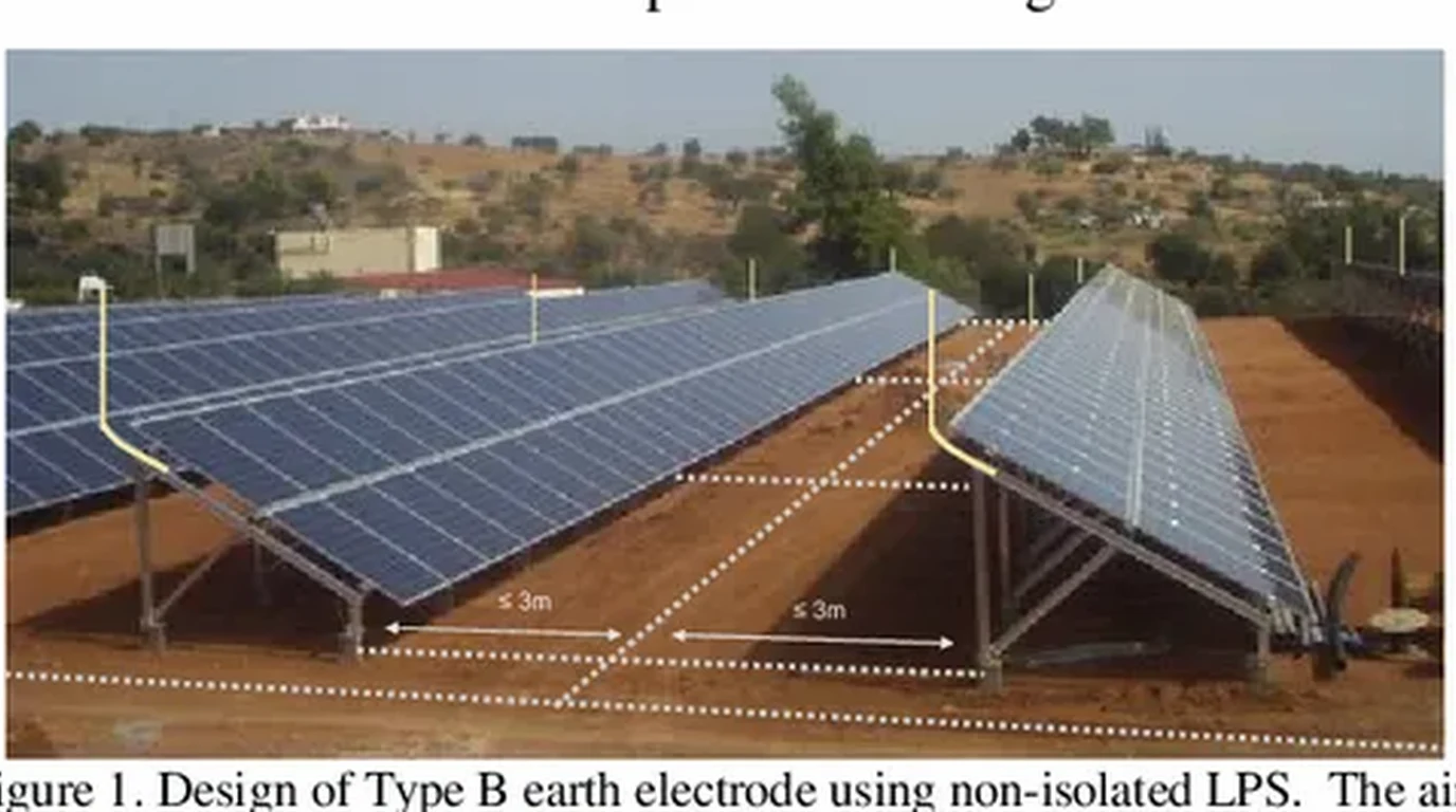
Solar arrays are uniquely exposed to atmospheric electrical discharges. Whether installed as elevated ground-mount structures across rural homesteads or mounted across commercial barn roofs, photovoltaic arrays present expansive metal planes elevated above surrounding terrain.
During a convective thunderstorm, a stepped leader descending from a cloud base seeks the path of least electrical resistance to ground. An ungrounded or poorly protected solar array acts as an open conductive antenna.
However, catastrophic equipment failure does not require a direct physical strike to the solar panels. Over ninety percent of lightning-related solar inverter and charge controller destruction is caused by indirect induced surges. A cloud-to-ground strike hundreds of feet away generates an intense, rapidly changing electromagnetic field () that induces thousands of volts across the DC circuit conductors, instantly puncturing MPPT semiconductor gates and pulverizing sensitive bypass diodes.
Building a resilient off-grid or grid-tied solar system demands a comprehensive, layered lightning mitigation strategy. This engineering guide examines direct interception physics per NFPA 780, inductive wire loop mitigation, earth grounding electrode design (), and the critical distinction between Type 1 and Type 2 DC Surge Protective Devices (SPDs).
Executive Summary: The Physics of Atmospheric Discharge
A cloud-to-ground lightning discharge is an instantaneous transfer of electrostatic charge spanning several coulombs across potential gradients exceeding one hundred million volts:
+-----------------------------------------------------------------------------------+
|               THE TWO THREAT MECHANISMS OF ATMOSPHERIC LIGHTNING                  |
+-----------------------------------------------------------------------------------+
|  1. Direct Physical Strike (The 10/350µs Impulse Waveform)                        |
|     • Current Peak: 30,000 to 200,000+ Amperes                                    |
|     • Thermal Energy: Explodes bypass diodes, melts aluminum frames, ignites roof |
|     • Defense Strategy: NFPA 780 Air Terminals (Lightning Rods) & Down Conductors |
|                                                                                   |
|  2. Indirect Induced Surges (The 8/20µs Transient Waveform)                       |
|     • Magnetic Coupling: Extreme dI/dt induces kilovolts across PV wire loops     |
|     • Ground Potential Rise: Soil voltage gradient drives reverse current back feed|
|     • Defense Strategy: Cable bundling, low-impedance ground grid, Type 1/2 SPDs   |
+-----------------------------------------------------------------------------------+
Standard residential circuit breakers and inverter internal fuses provide zero protection against lightning transients. Because a lightning waveform rises to peak voltage in less than eight microseconds (), mechanical breakers cannot physically trip fast enough to interrupt the arc. Effective defense relies strictly on solid-state surge clamping and dedicated low-impedance diversion paths.
Direct Strike Protection: NFPA 780 Air Terminals and Down Conductors
For large commercial ground mounts, off-grid field arrays, or structures in high keraunic regions (areas with high thunderstorm days per year, such as Florida and the Gulf Coast), physical lightning interception is governed by NFPA 780 (Standard for the Installation of Lightning Protection Systems).
The Rolling Sphere Method for Array Shielding
NFPA 780 defines interception zones using a geometric model known as the Rolling Sphere Method, which models an imaginary sphere with a radius of 150 feet (46 meters) rolling over the terrain and structures:
- Any point on the solar array that contacts the sphere’s surface is vulnerable to a direct lightning attachment.
- Elevated air terminals (copper or aluminum Franklin rods) are installed along the highest perimeter posts of the ground-mount racking.
- By spacing air terminals at calculated intervals, the rolling sphere rests solely on the tips of the rods, suspending a protective “shadow” zone above the sensitive glass modules:
Where (sphere radius), is the distance between masts, and is elevation.
+-----------------------------------------------------------------------------------+
|                 THE ROLLING SPHERE AIR TERMINAL SHIELDING ZONE                    |
+-----------------------------------------------------------------------------------+
|                  (Imaginary 150-ft Radius Lightning Sphere)                       |
|                             \                 /                                   |
|                              \               /                                    |
|         Air Terminal Rod      \             /      Air Terminal Rod               |
|              [ | ]             \___________/            [ | ]                     |
|                |                                          |                       |
|                |     ================================     |                       |
|                +----/       PROTECTED SOLAR ARRAY    \----+                       |
|                    /          (Inside Shadow)         \                           |
|                   +------------------------------------+                          |
|                  ///                                  ///                         |
|           Earth Ground                         Earth Ground                       |
+-----------------------------------------------------------------------------------+
Down Conductor Geometry and the Side-Flash Phenomenon
Once an air terminal intercepts a strike, the current must be carried to earth without jumping onto the solar electrical wiring. This hazard is known as a side-flash:
- Inductance Dominates Resistance: At lightning frequencies (megahertz equivalents), conductor impedance is governed almost entirely by inductive reactance () rather than DC resistance (). A sharp 90-degree right-angle bend in a down conductor introduces massive localized inductance, causing voltage to spike: With , a tiny bend generates a 30,000-Volt back-EMF pulse, causing lightning to jump through air onto nearby PV wires.
- Sweeping Radius Mandate: All lightning down conductors must maintain sweeping, gradual bends with a minimum radius of 8 inches (200 mm) and an included angle of no less than 90 degrees.
- Physical Separation: Maintain a minimum separation distance of at least 24 inches (60 cm) between raw lightning down conductors and DC string wiring or conduit.
Inductive Coupling Mitigation: Minimizing Wire Loop Area
While direct strikes capture public attention, indirect electromagnetic induction destroys far more off-grid equipment.

Faraday’s Law and the Dangerous “Open Loop”
When lightning strikes the earth several hundred yards from a solar array, the collapsing magnetic field sweeps through the physical space between the solar conductors:
Where is the induced voltage, is the enclosed loop area between conductors, and is the magnetic flux density.
If an installer routes the positive DC string conductor down the north side of a ground-mount rack and runs the negative return conductor down the south side, they create a massive open loop enclosing hundreds of square feet of magnetic catchment area:
+-----------------------------------------------------------------------------------+
|               INDUCTIVE WIRE LOOP ARCHITECTURE: BAD VS GOOD                       |
+-----------------------------------------------------------------------------------+
|  BAD: Massive Open Loop (Captures Hundreds of Volts/µs)                           |
|         [Module 1] ------> [Module 2] ------> [Module 3] ------> (+) Inverter     |
|             |                                                    |                |
|             |        <--- ENCLOSED MAGNETIC LOOP AREA --->       |                |
|             |                 (Picks up induced EMP)             |                |
|             v                                                    v                |
|            (-) <------------------------------------------------- Return Wire     |
|                                                                                   |
|  GOOD: Parallel Bundled Run (Near-Zero Loop Area, Faraday Neutralized)            |
|         [Module 1] ======> [Module 2] ======> [Module 3]                          |
|             (+) ===============================================> (+) Inverter    |
|             (-) ===============================================> (-) Inverter    |
|             (Positive, negative, and EGC cable-tied tightly touching together)    |
+-----------------------------------------------------------------------------------+
By zip-tying the positive string wire, negative return wire, and equipment grounding conductor (EGC) tightly together in parallel runs, the enclosed cross-sectional loop area collapses toward zero, slashing induced transient voltages by over ninety percent.
Surge Protective Devices: Type 1 vs Type 2 DC SPDs
Surge Protective Devices (SPDs) are the active solid-state sentinels that clamp transient overvoltages before they penetrate inverter power stages.
Metal Oxide Varistors and Gas Discharge Tubes
High-quality solar SPDs (such as the MidNite Solar MNSPD-300-DC / MNSPD-600-DC or Citel DS50VGPV) incorporate two complementary semiconductor technologies:
- Metal Oxide Varistors (MOVs): Zinc oxide grains that act as voltage-dependent non-linear resistors. Under normal 300V to 500V DC string voltage, the MOV presents gigohms of resistance. When lightning drives voltage above the Maximum Continuous Operating Voltage (), resistance collapses to near-zero within nanoseconds, shunting thousands of amperes safely to earth ground.
- Gas Discharge Tubes (GDTs): Sealed spark chambers filled with noble gas. GDTs handle extreme energy surges with zero continuous leakage current, preventing thermal runaway of the MOV during high ambient temperatures.
+-----------------------------------------------------------------------------------+
|                 TYPE 1 VS TYPE 2 DC SURGE PROTECTOR COMPARISON                    |
+-----------------------------------------------------------------------------------+
| Parameter                | Type 1 DC SPD                | Type 2 DC SPD           |
+--------------------------+------------------------------+-------------------------+
| Test Waveform Standard   | 10/350 µs (Direct Lightning) | 8/20 µs (Induced Surge) |
| Installation Location    | Array Combiner / Outdoor Box | Inverter DC Input Bus   |
| Peak Impulse Discharge   | $I_{\text{imp}} \ge 12.5\text{ kA}$ | $I_n = 20\text{ to } 40\text{ kA}$ |
| Response Speed           | $< 25\text{ Nanoseconds}$    | $< 25\text{ Nanoseconds}$|
| Primary Function         | Absorbs raw external strike  | Clamps residual voltage |
| NEC 2023 Designation     | Section 242.12 (Line Side)   | Section 242.14 (Load)   |
+--------------------------+------------------------------+-------------------------+
Two-Point SPD Protection Architecture
A professional solar installation requires two-point protection:
- Point 1 (At the Array): A Type 1 DC SPD installed inside the array combiner box or DC disconnect out at the ground mount. This stops the transient at the physical perimeter of the property.
- Point 2 (At the Inverter): A Type 2 DC SPD installed directly at the inverter’s DC input terminals inside the power room. This captures any secondary voltage wave induced along the long underground feeder conduit between the array and the house.
Earth Grounding Electrode Engineering: Achieving Less Than 25 Ohms
A surge protector is entirely useless without a low-impedance earth grounding electrode system. The SPD does not “destroy” lightning energy; it merely diverts it into the soil.
Soil Resistivity and Ground Rod Array Geometry
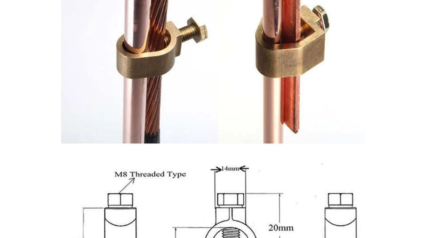
National Electrical Code (NEC 250.53) mandates that a single ground rod possessing a contact resistance to earth exceeding 25 Ohms must be augmented with a second electrode. In rocky, sandy, or dry clay homestead soil, a single 8-foot ground rod frequently measures between 80 and 300 Ohms, making it nearly useless for lightning dissipation:
To prevent ground rods from electrically interfering with each other, parallel rods must be separated by at least twice their driven depth:
- Two 8-foot (2.4m) copper-clad steel rods must be driven at least 16 feet (4.8m) apart.
- They must be bonded together using an unbroken, bare 6 AWG or 4 AWG solid copper conductor buried 18 to 24 inches underground.
+-----------------------------------------------------------------------------------+
|                  GROUND-MOUNT GROUNDING ELECTRODE SYSTEM                          |
+-----------------------------------------------------------------------------------+
|  [ Solar Array Steel Frame ]                                                      |
|         |                                                                         |
|         +--- #6 Bare Copper Equipment Grounding Conductor (EGC)                   |
|         |                                                                         |
|         v                                                                         |
|    (Ground Rod 1) <================ 16 Feet ================> (Ground Rod 2)      |
|    8-ft Deep in Well             Bare Copper Trench             8-ft Deep in Well |
|                                                                                   |
|         |                                                                         |
|         +=====> Continuous #6 Copper Grounding Electrode Conductor (GEC)           |
|                 Routed in same trench with DC conductors back to main house       |
|                 bonded to the main electrical service ground!                     |
+-----------------------------------------------------------------------------------+
Soil Conditioning: Bentonite and Chemical Ground Rods
In extremely rocky mountain locations where driving an 8-foot vertical rod is physically impossible:
- Horizontal Counterpoise Ground Ring: Trench a continuous perimeter ring around the array perimeter at least 30 inches deep using bare 2 AWG tinned copper cable.
- Bentonite Clay Slurry: Line the trench with sodium bentonite clay. Bentonite absorbs ambient ground moisture, expanding to form a permanent low-resistance conductive envelope around the copper wire that slashes ground impedance by fifty to seventy percent.
- Fall-of-Potential Earth Testing: Use an earth ground clamp tester (such as a Fluke 1630-2 FC) to verify that total system impedance measures under 10 to 25 Ohms before commissioning.
Ground Potential Rise and the Isolated Ground Rod Hazard
One of the most dangerous and widespread misconceptions in DIY off-grid solar is creating an isolated ground at the solar array.
Why “Island Grounding” Destroys Inverters
Installers frequently drive ground rods at the solar ground-mount array but fail to bond those rods back to the house’s main electrical service ground:
- A lightning strike hits the soil 200 feet from the solar panels.
- The current rushing through the soil creates a massive radial voltage gradient known as Ground Potential Rise (GPR).
- The ground potential at the solar array ground rods spikes to +50,000 Volts, while the ground rods back at the house 150 feet away remain at 0 Volts.
- The 50,000-Volt potential difference will force its way along the negative DC conductors, inverter communication cables (RS485/CAN bus), and Ethernet monitoring lines to reach the lower-potential house ground.
- Every semiconductor chip along that path is instantly vaporized.
+-----------------------------------------------------------------------------------+
|                 THE DESTRUCTIVE GROUND POTENTIAL GRADIENT LOOP                    |
+-----------------------------------------------------------------------------------+
|  [ Solar Array Ground Rod ]                               [ House Ground Rod ]    |
|   Voltage Spike: +50,000V                                   Voltage: 0V           |
|              |                                                   |                |
|              +--- 50kV Flashover along DC & Communication Cables -+               |
|                                     |                                             |
|                                     v                                             |
|                  BLOWN INVERTER MPPT & DESTROYED MOTHERBOARD                      |
+-----------------------------------------------------------------------------------+
The Code-Compliant Single-Point Ground Bond
To prevent Ground Potential Rise flashovers, NEC 250.50 mandates that all grounding electrodes on a premises must be bonded together into a single Grounding Electrode System:
- The array ground rods must be permanently bonded to the inverter and main service panel ground rod via an uninterrupted 6 AWG bare copper conductor run in the same underground trench as the DC power conductors.
- When the ground potential rises, the entire system floats up simultaneously to the same potential, maintaining zero differential voltage across internal electronics and completely preventing destructive flashover arcs.
Lightning Protection Engineering Checklist
Before lightning season arrives, verify that your solar array incorporates every layer of this defense hierarchy:
+-----------------------------------------------------------------------------------+
|                     ANNUAL SOLAR LIGHTNING SAFETY AUDIT                           |
+-----------------------------------------------------------------------------------+
| [X] Wire Loop Minimization: Positive and negative string conductors zip-tied      |
|     together along entire racking run to eliminate inductive loop catchment.      |
|                                                                                   |
| [X] Dual-Stage SPDs: Type 1 DC SPD installed at outdoor array combiner;          |
|     Type 2 DC SPD installed at indoor inverter MPPT DC disconnect.                |
|                                                                                   |
| [X] SPD Voltage Rating (MCOV): Varistor clamping voltage rated at least 20% to    |
|     30% above the array's maximum cold-weather Open Circuit Voltage (Voc).        |
|                                                                                   |
| [X] Earth Ground System: Dual 8-foot copper ground rods spaced at least 16 feet    |
|     apart, achieving verified earth impedance under 25 Ohms.                      |
|                                                                                   |
| [X] Single-Point Ground Bond: Remote array ground rods bonded back to main house  |
|     service panel ground with continuous #6 bare copper to eliminate GPR loops.   |
|                                                                                   |
| [X] Communication Line Isolation: RS485 and Ethernet cables equipped with RJ45   |
|     gas discharge tube surge suppressors or replaced with non-conductive fiber.   |
+-----------------------------------------------------------------------------------+
By engineering low-impedance dissipation pathways, minimizing electromagnetic loop area, and bonding all grounding electrodes into a unified equipotential plane, an off-grid solar installation can survive severe direct and indirect atmospheric lightning strikes season after season.