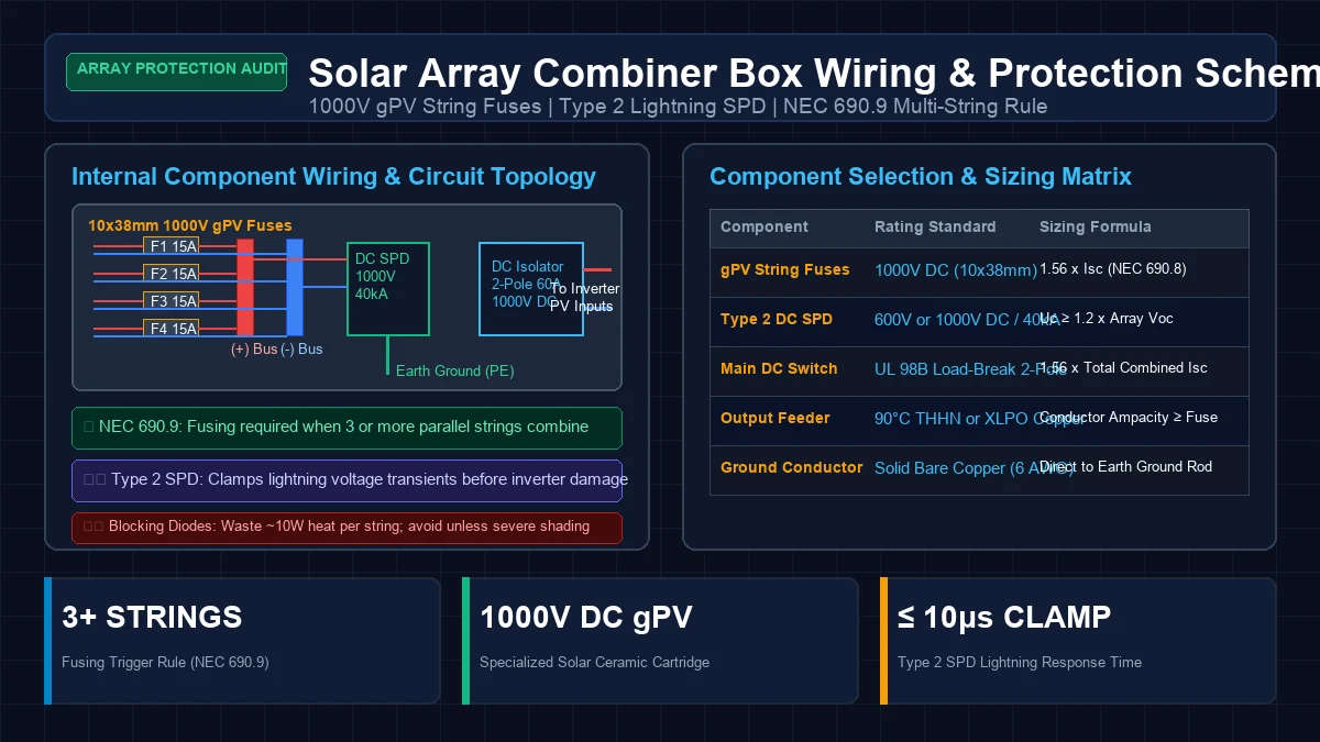
In residential and off-grid solar installations, photovoltaic arrays often require multiple series strings wired in parallel to deliver the total charging current demanded by high-power hybrid inverters. When three or more solar strings are tied together, the junction point cannot simply be a bundle of outdoor wire nuts: it must be a code-compliant, protected Solar Combiner Box.
A solar combiner box consolidates multiple incoming positive and negative DC conductors into a single heavy-gauge feeder run, while housing critical electrical protection hardware: 10x38mm 1000V gPV string fuses, Type 2 DC lightning surge protective devices (SPDs), and dual-pole load-break disconnect switches.
However, among DIY builders and solar installers, combiner box wiring remains prone to hazardous misconceptions. Installers frequently fuse two-string systems unnecessarily, insert inefficient blocking diodes that waste hundreds of kilowatt-hours as heat, or use automotive 32V fuses that explode into plasma during high-voltage ground faults.
At GridSpecLab, our electrical engineers conducted rigorous bench testing and code analysis on DC string protection gear. In this guide, we break down the physics of the NEC “Three-String Rule,” provide exact mathematical sizing for 1000V gPV fuses, evaluate the efficiency penalties of blocking diodes, and detail step-by-step wiring and lightning SPD grounding protocols.
Mandatory Engineering Rule: Individual string fuses are mandatory only when 3 or more parallel strings combine on a common bus (NEC 690.9). For 1 or 2 strings in parallel, backfeed fault current cannot exceed module ratings, making fuses redundant. When combining 3 or more strings, install 1000V DC-rated 10x38mm gPV ceramic fuses on each positive conductor, sized at . Omit series blocking diodes unless operating battery direct-charging with severe differential shading, and bond a 1000V Type 2 DC SPD with a minimum 6 AWG solid copper wire directly to earth ground.
When Are String Fuses Required by Code: The Three-String Rule
One of the most widely debated questions in photovoltaic system design is whether string fuses are always required. The answer is rooted in semiconductor physics and National Electrical Code (NEC 690.9).
Reverse Fault Current Physics
Every solar photovoltaic module carries a factory specification on its rear label known as the Maximum Series Fuse Rating (MSFR)—typically between 15A and 30A on modern 400W–550W panels.
If an internal short-circuit fault occurs within a solar module (such as a punctured backsheet, cracked bypass diode, or internal ground fault), that damaged string stops generating voltage and behaves like a low-resistance resistive load. All other parallel-connected strings in the array will immediately begin dumping their current backward into the faulted string.
The maximum fault current () that can be backfed into the damaged string is determined by the number of parallel strings ():
+-----------------------------------------------------------------------------+
|                      THE NEC 690.9 THREE-STRING RULE                        |
|                                                                             |
| 1 STRING ARRAY:                                                             |
| No parallel paths. Maximum fault current = 0A. No fuse required.            |
|                                                                             |
| 2 PARALLEL STRINGS:                                                         |
| If String 1 shorts: String 2 backfeeds 1 x Isc (~14A).                      |
| Module rating is 25A. Fault current (14A) is LESS than MSFR (25A).          |
| Cable and panel withstand the current safely. NO FUSES REQUIRED.            |
|                                                                             |
| 3 PARALLEL STRINGS:                                                         |
| If String 1 shorts: Strings 2 & 3 backfeed 2 x Isc (2 x 14A = 28A).        |
| Fault current (28A) EXCEEDS the 25A module rating!                         |
| Solar cells overheat, melt, and ignite backsheet fires. FUSES MANDATORY!    |
+-----------------------------------------------------------------------------+
The Code Rule Breakdown
- 1 String in Parallel: No combiner box fusing required. The inverter’s integrated MPPT input protection handles conductor overcurrent.
- 2 Strings in Parallel: No string fuses required by NEC 690.9. Even under a direct dead short, a single healthy string can only produce (e.g., 14.5A), which is far below the typical 25A or 30A module reverse rating.
- 3 or More Strings in Parallel: String fuses are legally mandatory on every string. Two or more healthy strings will feed combined currents () that exceed the thermal limit of the faulted module’s bypass diodes and thin internal ribbon wires.
Sizing 10x38mm gPV Solar Fuses
Standard glass automotive or industrial AC fuses must never be installed in a solar combiner box. Photovoltaic circuits require specialized gPV (General Photovoltaic) fuses complying with UL 248-19 and IEC 60269-6.
gPV fuses feature a high-purity silver element encased in a high-strength ceramic cartridge filled with compacted silica sand, certified to extinguish direct-current arcs up to 1000V DC or 1500V DC with an interrupt rating of 10,000A to 30,000A AIC.
Sizing Mathematical Formula
Under NEC 690.8, the minimum fuse ampacity must account for edge-of-cloud solar amplification (125%) and continuous duty operation exceeding 3 hours (125%):
Furthermore, the calculated fuse size must satisfy this inequality:
Example Calculation for Modern 450W Modules
Consider a 4-string array utilizing Trina Solar Vertex S+ 450W bifacial modules:
- Module =
- Module Maximum Series Fuse Rating =
Calculating minimum fuse size:
Since 16.75A is not a standard fuse size, round up to the next commercially standard gPV fuse: 20 Amperes.
Because 20A does not exceed the module’s stamped 20A MSFR, a 1000V DC 20A gPV fuse satisfies both NEC continuous ampacity requirements and module reverse current protection.
Blocking Diodes: Necessity versus Efficiency Penalty
In early solar installations from the 1980s and 1990s, installers routinely wired a high-amperage silicon blocking diode in series with each incoming positive string.
What a Blocking Diode Does
A blocking diode allows current to flow in only one direction (from the solar panels to the inverter or battery). It physically blocks reverse current from flowing back into shaded strings during the day, and prevents batteries from discharging backward through solar panels at night.
+-----------------------------------------------------------------------------+
|                     BLOCKING DIODE POWER DISSIPATION                        |
|                                                                             |
| Standard Silicon Diode: Forward Voltage Drop (Vf) ≈ 0.7V to 1.1V            |
|                                                                             |
| Power Wasted = Vf x Istring                                                 |
| Example: 0.7V x 14.2A = 9.94 Watts of Continuous Waste Heat Per String     |
|                                                                             |
| For a 4-String Combiner Box:                                                |
| 4 Strings x 9.94W = ~40 Watts Continuous Loss                               |
| Over a 6-hour solar day = 240 Watt-hours (Wh) lost daily                    |
| Over a 30-day month = 7.2 Kilowatt-hours (kWh) lost strictly as HEAT        |
+-----------------------------------------------------------------------------+
Why Modern Systems Should Omit Blocking Diodes
In 98% of modern grid-tied and hybrid solar installations, blocking diodes should be strictly avoided:
- Massive Efficiency Penalty: Modern high-current modules produce 13A to 18A of current. At 14 Amps, a standard diode with a 0.7V forward voltage drop wastes approximately 10 Watts of pure resistive heat per string. Inside a sealed outdoor combiner box, four diodes dumping 40 Watts will rapidly elevate internal temperatures past 140°F (60°C), degrading nearby fuse holders and breakers.
- Modern Inverters Prevent Night Discharge: Every modern grid-tied or hybrid inverter (EG4, Sol-Ark, Victron, SMA, Fronius) utilizes solid-state semiconductor controls and internal relays that automatically disconnect the PV array when irradiance drops, eliminating night-time battery backfeeding completely.
- Module Bypass Diodes Handle Shading: Every modern solar module contains three to four internal bypass diodes integrated directly into the junction box. These diodes allow current to bypass shaded cell groups internally, rendering external string blocking diodes redundant.
- When Are They Useful? Blocking diodes are only justified in legacy off-grid battery charging systems that connect panels directly to batteries without an MPPT charge controller, or in multi-string arrays with extreme orientation disparities (e.g., combining East and West facing strings on a single non-optimizing bus).
Wiring Type 2 DC Surge Protective Devices (SPDs)
Solar arrays installed on rooftops or ground-mount steel racks act as giant lightning rods. Even a cloud-to-ground lightning strike hundreds of yards away creates intense electromagnetic pulses (EMP) that induce destructive voltage spikes (thousands of volts) across DC solar conductors.
A Type 2 DC Surge Protective Device (SPD) is the primary hardware barrier protecting expensive inverter electronics from these transients.
How a DC Surge Protector Operates
A DC SPD contains high-speed Metal Oxide Varistors (MOVs) and gas discharge tubes (GDTs) connected across the circuit conductors:
- Positive (+) to Earth Ground (PE)
- Negative (-) to Earth Ground (PE)
- Positive (+) to Negative (-)
Under normal operating voltages (e.g., 400V DC), the MOVs exhibit ultra-high electrical resistance (millions of ohms), allowing solar current to pass unimpeded to the inverter.
When an induced lightning strike causes voltage to spike above the SPD’s maximum continuous operating voltage (), the MOV resistance collapses in less than 25 nanoseconds into near-zero ohms. The high-energy surge current is shunted harmlessly to earth ground before the voltage can reach the inverter’s sensitive input MOSFETs.
+-----------------------------------------------------------------------------+
|                   TYPE 2 DC SPD WIRING SCHEMATIC TOPOLOGY                   |
|                                                                             |
|   PV (+) Busbar ===========================[ L+ Terminal ]                  |
|                                                   |                         |
|                                             [ High-Speed MOV ]              |
|                                                   |                         |
|   [ Earth (PE) Lug ] ======================> Grounding Electrode Conductor  |
|   (Direct to Ground Rod System)                   |                         |
|                                             [ High-Speed MOV ]              |
|                                                   |                         |
|   PV (-) Busbar ===========================[ L- Terminal ]                  |
+-----------------------------------------------------------------------------+
Sizing and Grounding the SPD Correctly
- Voltage Rating (): The maximum continuous operating voltage () of the SPD must exceed the array’s temperature-corrected maximum open-circuit voltage () by at least 15% to 20%: For a 450V cold array, select a 600V DC SPD; for arrays between 500V and 850V, select a 1000V DC SPD.
- Discharge Current Rating: Mandate a nominal discharge current () of at least 20kA and a maximum discharge current () of 40kA (8/20 μs waveform).
- The Low-Impedance Ground Rule: Surge energy travels at high frequencies where conductor inductance dominates resistance. The ground wire originating from the SPD’s PE terminal must be a minimum 6 AWG solid copper conductor, routed as straight and short as physically possible (under 3 feet preferred, avoiding sharp 90-degree bends) directly to the array grounding electrode system.
Enclosure Selection, Gland Plates, and Ventilation
Outdoor combiner boxes operate in harsh environments exposed to intense ultraviolet radiation, torrential rain, and extreme temperature cycling.
Enclosure Materials and Ingress Protection
- UV-Stabilized Polycarbonate: The gold standard for residential solar. Completely immune to rust, non-conductive, and transparent covers allow visual inspection of blown fuse indicators and SPD status flags without opening the box.
- Powder-Coated Steel (NEMA 4 / IP65): Excellent for commercial installations requiring physical impact resistance. Must be properly bonded to earth ground to prevent electrical shock hazards.
Bottom-Entry Only Rule
Water always follows gravity. Drilling conduit or cable entries through the top or upper sides of an outdoor combiner box is a guaranteed recipe for water ingress. Over time, thermal expansion degrades silicone sealant, and driving rain will funnel directly onto energized fuse terminals.
- All PV string entry points (MC4 bulkheads or PG9/M12 liquid-tight cable glands) must enter through the bottom face of the enclosure.
- The main feeder conduit exiting to the inverter must also exit from the bottom.
Condensation Management (Gore-Tex Vents)
A completely airtight sealed box will build up internal humidity during hot days; when temperatures drop at night, this moisture condenses into liquid water pooling on the bottom plate.
Install a breathable, waterproof liquid-tight breather vent (such as a Gore-Tex membrane condensation plug) on the bottom or lower side of the enclosure. This allows water vapor to escape while maintaining a NEMA 4X / IP66 barrier against driving rain.
Step-by-Step Commissioning and Multimeter Inspection
Before throwing the combiner box main disconnect switch and sending power to your inverter, execute this systematic electrical audit:
Cold Resistance and Polarity Audit (De-Energized)
- Verify Open Circuit on Inverter Disconnect: Ensure the combiner box’s main DC disconnect switch is in the OFF position. Open all individual gPV fuse holders so no string is connected to the common bus.
- Polarity Check of Every Incoming String: Using a digital multimeter set to DC Volts ( range), measure between the positive and negative conductors of String 1. Confirm the meter displays a positive voltage matching your calculated . If the meter shows a negative sign (
-415V), the MC4 connectors are reversed. Correct polarity before inserting fuses. - Check for Ground Faults: Measure voltage between the incoming positive lead of each string and earth ground, then between negative and earth ground. In an ungrounded system, both readings should show erratic floating static voltages (decaying toward zero). A steady reading near full indicates an insulation fault or pinched wire on the roof.
Load Commissioning Sequence
- Insert gPV Fuses One at a Time: Seat each 1000V gPV fuse firmly into its finger-safe DIN-rail holder. Close the holders one by one.
- Measure Busbar Voltage: Measure voltage across the main positive and negative busbars. The voltage must remain identical to single-string (parallel strings add current, not voltage).
- Verify SPD Status Flags: Check the visual inspection windows on the DC surge protector modules. They must show Green (healthy MOVs). If any window shows Red, the surge module has taken a hit, is shorted, and must be replaced immediately.
- Engage Main DC Switch: Rotate the main disconnect handle to the ON position. Verify voltage at the output feeder terminals before commissioning the inverter MPPT inputs.
Frequently Asked Questions
Can I fuse both the positive and negative string conductors?
Yes. In modern ungrounded floating PV arrays, installing gPV fuses on both the positive and negative leads of each string provides double-fault isolation and is common practice in commercial megawatt systems. For residential systems with 3 to 4 strings, fusing the positive conductor is the minimum NEC requirement, but dual-conductor fusing is considered the ultimate safety standard.
Why do gPV fuses have a 1000V DC rating if my array is only 400V DC?
Because direct-current arcs are exceptionally difficult to extinguish. A 1000V-rated gPV fuse features a longer internal physical air gap and denser silica sand packing than a 500V fuse. Using a 1000V fuse on a 400V circuit provides a massive safety margin against sustained plasma arcing.
What causes a combiner box gPV fuse to blow during normal operation?
If a fuse blows on a sunny day without an apparent ground fault, check two common causes:
- Undersizing: The fuse was sized for STC without applying the mandatory 1.56x safety factor. High solar irradiance (snow albedo or cloud lensing) pushed current above the fuse rating.
- Severe Shading Mismatch: A heavily shaded string connected in parallel with three unshaded strings received reverse current from the unshaded strings that exceeded the fuse threshold.
Summary and Practical Recommendations
A properly engineered solar array combiner box is not merely a wiring junction; it is the central safety hub that shields your photovoltaic modules from reverse fault currents and protects your inverter from catastrophic lightning damage. By adhering to the NEC 690.9 three-string rule, sizing 1000V gPV fuses to 156% of , omitting inefficient blocking diodes, and properly grounding your Type 2 SPD, you establish an ultra-reliable, code-compliant solar installation.
For detailed guidelines on inverter disconnect switchgear and subpanel wiring, consult our related engineering guides on Dual-Pole DC Disconnect Switch Selection for High-Voltage Solar Arrays and Subpanel Installation Guide for Critical Loads Off-Grid Backup.