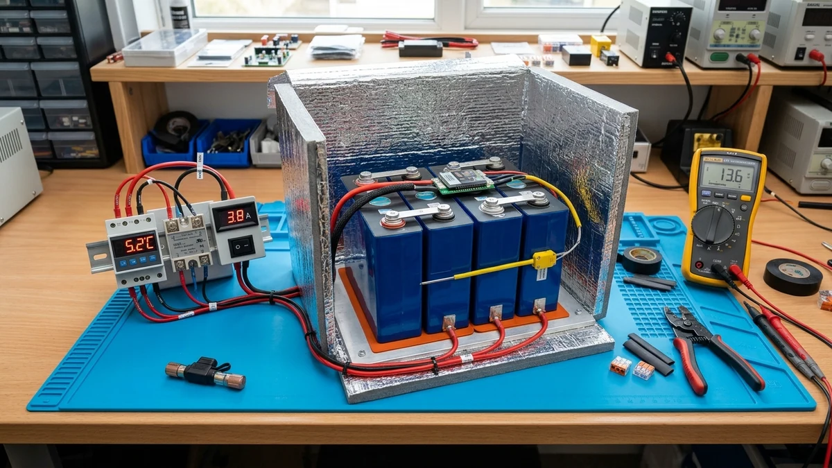
Lithium iron phosphate (LiFePO4) chemistry delivers unmatched thermal stability, non-combustible safety characteristics, and over a decade of cycle life. However, it harbors a severe Achilles heel: sub-zero charging vulnerability. While a LiFePO4 battery bank can safely discharge in sub-freezing temperatures down to -20°C (-4°F), attempting to charge the cells when their internal core temperature drops below 0°C (32°F) initiates irreversible electrochemical destruction.
For off-grid homesteaders, RV travelers, and cold-climate solar installations where battery storage resides in an unconditioned shed, garage, or vehicle chassis, an automated thermal management system is essential.
This guide delivers an end-to-end engineering blueprint for designing, calculating, and wiring a low-voltage silicone heating pad system. We break down the physics of lithium plating, calculate the thermal energy required to warm prismatic cells, evaluate aluminum heat spreader mechanics, and provide complete schematics for both BMS-controlled and standalone thermostat architectures.
Electrochemical Hazards of Sub-Zero Lithium Plating
Understanding why low-temperature charging is catastrophic requires examining the kinetics of lithium intercalation into synthetic graphite.
Sluggish Ion Diffusion and Solid Metallic Plating
Under normal operating temperatures (15°C to 35°C), lithium ions de-intercalate smoothly from the cathode, travel across the liquid organic electrolyte, and slip between the graphene sheets of the graphite anode.
When cell core temperatures drop below 0°C:
- Electrolyte Viscosity Spikes: The liquid organic carbonate electrolyte thickens, severely impeding the drift velocity of lithium ions ().
- Charge-Transfer Resistance Escalates: The kinetic energy required for lithium ions to shed their solvation sheath and penetrate the Solid Electrolyte Interphase (SEI) layer increases exponentially.
- Anode Overpotential: Because ions cannot enter the graphite lattice as fast as incoming charging current arrives, the electrical potential of the graphite anode drops below 0V relative to the reference electrode.
When the anode potential drops below zero volts, lithium ions take the path of least electrical resistance: instead of intercalating into the graphite, they reduce directly into solid metallic lithium on the outer surface of the anode:
NORMAL CHARGING (>5°C):
Cathode ──[Li+ Ions]──► Liquid Electrolyte ──► Intercalated into Graphite Anode

FREEZING CHARGING (≤0°C):
Cathode ──[Li+ Ions]──► Sluggish Electrolyte ──► Metallic Lithium Dendrites Plated on Surface
                                                          │
                                                          ▼
                                            Separator Punctured = Dead Short!
The Inherent Asymmetry: Discharging vs Charging
A common point of confusion is why LiFePO4 can discharge at -20°C while charging is strictly prohibited at 0°C.
During discharge, lithium ions leave the graphite anode and travel back to the cathode. Stripping lithium out of the anode is thermodynamically favored even in cold conditions; the only consequence is reduced cell voltage and higher internal resistance ().
During charging, forcing ions into the cold anode causes metallic plating. Once plated, these metallic deposits form microscopic, razor-sharp needle-like crystals known as dendrites. Over successive charge cycles, dendrites grow across the microporous separator film until they pierce through to the cathode, causing a permanent internal dead short-circuit, catastrophic cell self-discharge, and potential thermal runaway.
Sizing Heater Wattage and Surface Watt Density
To design an effective heating system, you must calculate the total heat energy () required to elevate the battery mass from ambient winter conditions up to a safe charging threshold (+5°C / 41°F) within an acceptable time window.
Thermodynamic Heating Energy Equation
The fundamental heat equation governs thermal sizing:
Where:
- = Total thermal energy required (Joules)
- = Mass of the battery bank (kg)
- = Specific heat capacity of prismatic LiFePO4 cells ()
- = Temperature rise required (, in Kelvin or °C)
To convert energy into continuous electrical heating power (, in Watts) for a desired heating duration (, in seconds):
Where is the thermal transfer efficiency factor (typically 0.70 to 0.80 for well-insulated battery boxes).
Engineering Calculation: 16S 48V 280Ah Battery Bank
Let us evaluate a standard 16S 48V DIY pack using EVE LF280K cells:
- Individual cell weight: 5.42 kg
- Total cell mass ():
- Initial ambient shed temperature: -10°C (14°F)
- Safe charging target temperature: +5°C (41°F)
- Temperature differential ():
- Desired warm-up time (): 2.5 hours = 9,000 seconds
- Thermal insulation efficiency (): 75% (0.75)
Calculating thermal energy:
Calculating continuous electrical heating power:
Dividing across 16 cells yields:
This validates the standard industry rule of thumb: 10 to 15 Watts per 280Ah cell (160W to 240W total for a 16S 48V bank; 40W to 60W total for a 4S 12V bank).
Surface Watt Density Limits
Silicone heating pads are rated by surface watt density (), expressed in Watts per square inch () or Watts per square centimeter ().
High-density industrial pads (such as 3D printer bed heaters rated at ) get scorching hot within seconds. If placed near a battery, they melt the blue PET protective film and overheat the outer electrode layers before internal heat can conduct into the cell core.
For LiFePO4 battery heating, always select ultra-low watt density pads:
- Maximum Recommended Density: Under 0.40 W/in² (under 0.06 W/cm²)
- Operating Surface Temperature: Maintained below 35°C to 40°C (95°F to 104°F)
Heat Transfer Physics and Aluminum Spreader Plates
Applying a silicone heating pad directly against the thin aluminum casing of a prismatic cell is an engineering error.
The Localized Hotspot Dilemma
Prismatic cells possess anisotropic thermal conductivity:
- Heat conducts relatively well along the planar surface of the electrode sheets ().
- Heat conducts poorly perpendicular across the wound layers of separators and electrolyte films ().
If a heating element touches the cell wall directly, the aluminum casing directly above the heater reaches 50°C, while the cell core remains frozen at -5°C. A single external BMS thermistor will read artificially elevated temperatures, tricking the BMS into enabling high-current charging while the core is still cold enough to plate lithium.
DIRECT PAD CONTACT (DANGEROUS):
[Cell Wall] ────► [45°C Hotspot] ─── (BMS sensor reads 35°C, enables charge!)
                      ▲
           [Small Silicone Pad]
                  (Core is still frozen at -4°C = Lithium Plating!)

ALUMINUM SPREADER PLATE (ENGINEERING STANDARD):
[Cell 1]  [Cell 2]  [Cell 3]  [Cell 4]  ...  [Cell 16]
════════════════════════════════════════════════════════════
       3mm to 6mm 6061 Aluminum Heat Spreader Plate
════════════════════════════════════════════════════════════
           [Low-Density Silicone Heating Pads]
      100% uniform gentle warmth, zero localized thermal spikes!
Heat Spreader Construction Specifications
- Plate Material: 6061-T6 aluminum sheet, minimum 3.0 mm (0.12 in) thick; 4.76 mm to 6.35 mm (3/16 to 1/4 in) is optimal for large 16S packs. Aluminum exhibits a thermal conductivity of , over 100 times higher than battery core cross-conduction.
- Mounting Location: Place the aluminum spreader plate beneath the battery bank (under-floor heating) or along the broad longitudinal side of the pack. Under-floor heating utilizes natural thermal buoyancy (convection rises upward through the cells).
- Thermal Interface Material (TIM): Apply an ultra-thin silicone thermal transfer mat (0.5 mm) or thermal conductive silicone adhesive between the heating pad and the aluminum plate to eliminate insulating air gaps.
- Dielectric Isolation: Ensure the cell bottom insulator (0.5mm FR4 fiberglass or high-density fish paper) sits between the aluminum plate and the cell casings to prevent abrasive metal-on-metal electrical contact.
Control Architecture: BMS Dry Contacts vs Standalone Thermostats
Automating heating pad operation requires a reliable control loop that prevents parasitic over-draining while guaranteeing charge safety.
CONTROL METHOD COMPARISON:

1. Smart BMS Auxiliary Output (JK, Daly, Seplos, JBD):
   ├── Native integration with internal BMS temperature sensors
   ├── Automatically inhibits charging FETs until target temp is reached
   ├── Built-in low-voltage cutoffs
   └── Dedicated heating port drives an external relay

2. Dual-Stage Standalone Thermostat (STC-1000 / Inkbird):
   ├── Independent hardware redundancy (failsafe if BMS locks up)
   ├── Fully programmable setpoints and deadbands (e.g., ON at 2°C, OFF at 8°C)
   ├── Requires external NTC thermistor placement
   └── Universal compatibility with any battery bank
Implementing BMS Dry Contact Heating
Modern smart BMS units—such as the JK Inverter BMS, Seplos Mason V3, or Daly Smart BMS with heating function—feature a dedicated auxiliary output port (often labeled HEAT+ / HEAT- or a dry-contact relay).
The logic works as follows:
- When charge current is detected from an inverter or solar charge controller, the BMS checks its NTC temperature probes.
- If temperature is below (e.g., 2°C):
- The BMS disables charging FETs to prevent incoming current from reaching the cells.
- The BMS energizes the heating output, routing incoming power directly into the silicone heating pads.
- Once the cell probes register (e.g., 8°C to 10°C):
- The BMS de-energizes the heating pads.
- The BMS opens the charge FETs, permitting full charging current into the cells.
Implementing Standalone Digital Thermostats (STC-1000)
If using a standard BMS without native heating control, an industrial digital temperature controller like the STC-1000 (12V, 24V, or 48V DC version) provides robust, independent control:
- Heating Trigger Setpoint (): Set to (41°F).
- Hysteresis / Differential Value (): Set to .
- Operating Cycle: The heater turns ON when temperature falls to () and shuts OFF when temperature rises to .
- Sensor Placement: Mount the NTC thermistor probe in the coldest corner of the battery enclosure, clamped directly against the aluminum cell body (shielded from direct air convection).
Energy Source Strategy: Solar PV Power vs Battery Reserves
A critical engineering decision is determining where the electrical energy to run the heaters originates.
| Heating Strategy | Power Source | Pros | Cons | Ideal Application |
|---|---|---|---|---|
| Solar PV Diverter | Solar Array (via Aux CC output or PV voltage sensing) | Zero battery drain; runs purely on daytime excess solar energy. | Cannot pre-heat before sunrise; morning solar charging is delayed. | Remote off-grid cabins, seasonal solar setups. |
| Battery Reserve with LVD | Main Battery Bank (via DC busbar) | Can pre-heat overnight so battery is warm the instant morning sun arrives. | Parasitic drain can empty the battery during multi-day blizzards without sun. | Full-time homesteads with backup generators or large battery reserves. |
| Hybrid AC/DC Shore Power | Grid / Shore Power / Inverter Charger | Instant, high-capacity heating regardless of solar conditions. | Requires grid connection or automated generator auto-start (AGS). | RVs in campgrounds, mobile workshops. |
Preventing the Death Spiral with Low Voltage Disconnect (LVD)
If powering heaters from the battery bank, you must incorporate a hardware Low Voltage Disconnect (LVD):
- For a 48V pack: Set LVD cutoff at 49.6V (3.10V per cell).
- If persistent blizzard conditions drop battery voltage below 49.6V, the LVD cuts power to the heaters entirely.
Allowing heaters to pull a depleted battery down to 0% SoC in sub-zero weather causes catastrophic copper dissolution and permanent cell failure. It is far safer to let a disconnected battery freeze in a dormant, non-charging state than to drain it to zero volts.
Complete Wiring Schematic and Electrical Protection
Below is the definitive wiring architecture for a 48V DIY LiFePO4 battery heating system utilizing a DC solid-state relay (SSR), an STC-1000 controller, and an aluminum spreader plate.
                  48V DC BUSBAR (+)
                          │
                   [15A MIDI Fuse]
                          │
         ┌────────────────┴────────────────────────┐
         │                                         │
   (Pin 1: Power +)                         (SSR Input +)
   ┌─────────────┐                          ┌─────────────┐
   │  STC-1000   │                          │  DC-DC SSR  │
   │ Controller  │                          │ (Relay Pin) │
   │             │                          └──────┬──────┘
   │  (Relay 1)  │───[Pos Signal Wire]─────────────┘
   │  (Relay 2)  │───┐
   └──────┬──────┘   │
          │          │
   (Pin 2: Power -)  │
          │          │
   48V BUS (-)       │
                     ▼
          [Normally Closed Thermal Switch] (45°C Fail-safe)
                     │
         ┌───────────┴───────────┐
         │                       │
   [Heater Pad 1]          [Heater Pad 2]
    (24V 100W)              (24V 100W)  <── Wired in Series for 48V
         │                       │
         └───────────┬───────────┘
                     │
              48V DC BUSBAR (-)
Bill of Materials (BOM) for 16S 48V System
- Silicone Heating Pads: 2× 24V 100W flexible silicone heating pads (, wired in electrical series to operate on 48V nominal, total 200W).
- Heat Spreader Plate: 1× 6061-T6 aluminum sheet ().
- Switching Relay: 1× DC-to-DC Solid State Relay (e.g., Fotek or Crydom DC-DC SSR, rated 60VDC 25A minimum) with a small clip-on aluminum DIN-rail heatsink.
- Digital Controller: 1× STC-1000 (wide-input DC 12V–72V version, or standard 12V version powered via a 48V-to-12V buck converter).
- Circuit Protection: 1× 15A MIDI or inline automotive fuse holder with 15A fuse on the positive supply line.
- Thermal Safety Limit Switch: 1× KSD301 Bimetal Thermostat switch (Normally Closed, opening at 45°C / 113°F), epoxied directly to the aluminum heat spreader plate as an analog hardware fail-safe against stuck relays.
- Wiring: 14 AWG high-temperature silicone-insulated copper wire (rated 200°C) for heating circuits; 18 AWG for thermostat sensing.
- Enclosure Insulation: 25mm to 50mm foil-faced polyisocyanurate (PIR) rigid foam board () lining all six internal surfaces of the battery cabinet.
Testing and Low-Temperature Verification Protocol
Before exposing your battery bank to sub-zero winter temperatures, perform a comprehensive bench test:
Verification Protocol Checklist
- Benchtop Sensor Calibration: Place the NTC thermistor probe in a slurry of ice water (). Verify the STC-1000 or BMS displays . Adjust temperature offset calibration if necessary.
- Relay Activation Handshake: Warm the sensor with your fingers above to confirm the relay disengages. Chill the sensor with freeze spray or ice to confirm crisp engagement at .
- Thermal Distribution Verification: Power the heating pads on for 20 minutes while monitoring the aluminum spreader plate with a handheld thermal imaging camera or infrared pyrometer. Confirm temperature across the entire plate remains uniform within , with zero localized hot spots exceeding .
- Analog Fail-Safe Test: Temporarily bypass the thermostat to force continuous heating. Verify that the KSD301 45°C bimetal switch reliably breaks the circuit before the aluminum plate reaches .
- BMS Charge Inhibit Test: Verify that while the heating pads are energized, the BMS charging MOS/contactor remains open, confirming that zero solar charge current can enter the cells until the low-temperature setpoint is cleared.
Technical Summary
Sub-zero charging is the fastest method to permanently ruin a high-value DIY LiFePO4 battery bank. By installing a precision-engineered thermal management system consisting of ultra-low density silicone heating pads (10W to 15W per cell), an aluminum heat spreader plate (minimum 3mm thick), 45°C redundant bimetal safety cutoffs, and polyisocyanurate cabinet insulation, you ensure dependable off-grid energy storage throughout the most brutal winter conditions.