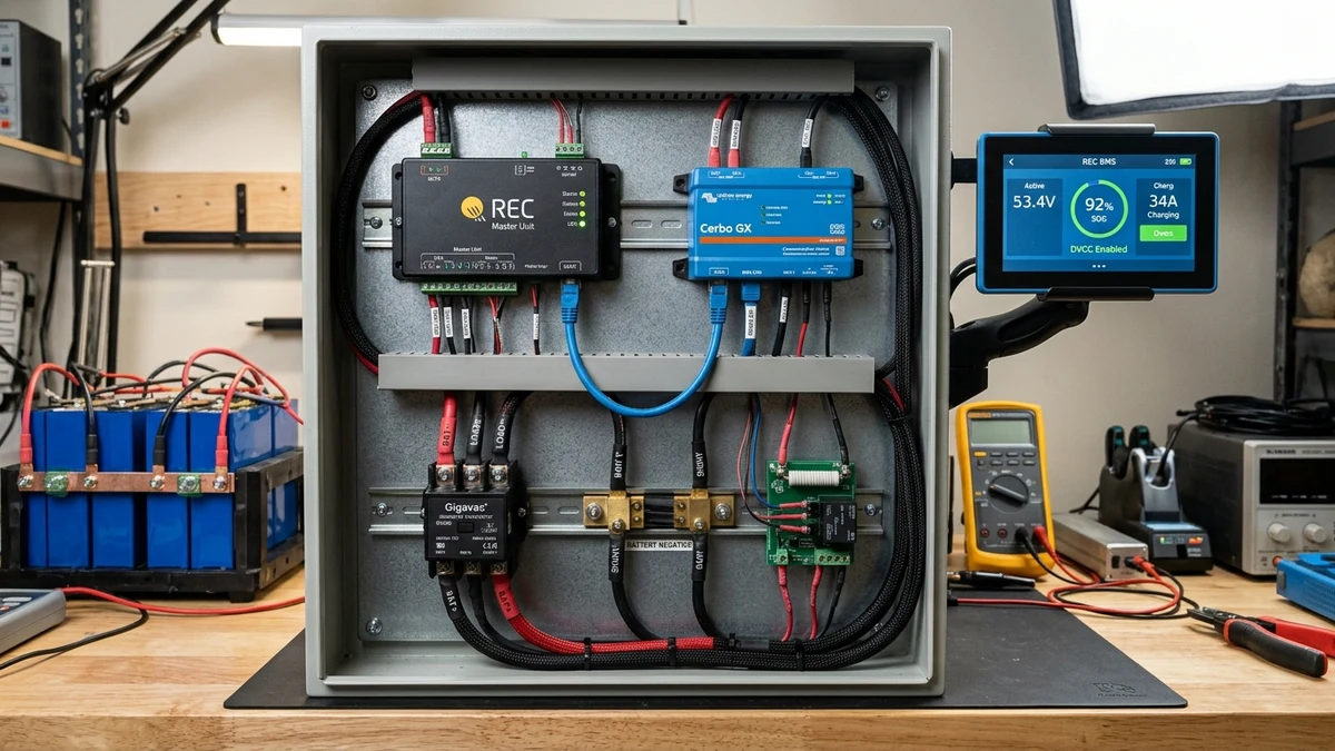
In mission-critical marine electrical networks, off-grid expedition vehicles, and high-capacity residential battery storage, relying on standard internal-FET battery management systems introduces a single point of failure. If an internal MOSFET fails shorted under heavy load, the battery can neither disconnect an overcharging alternator nor stop a dead short circuit.
The Slovenian-engineered REC Q-BMS (and its siblings, the REC Active BMS and SI-BMS) represents the industrial benchmark for DIY lithium iron phosphate (LiFePO4) installations. By decoupling sensing logic from power switching, the REC Q-BMS drives heavy-duty external magnetic latching contactors (such as Gigavac or Blue Sea Systems units) and communicates natively with the Victron Energy ecosystem via CAN-bus 2.0B.
When paired with a Victron Cerbo GX running Venus OS, the REC BMS transforms raw prismatic cells into an intelligent, closed-loop managed battery bank. This engineering guide details the complete hardware wiring, CAN-bus pinouts, contactor pre-charge sequencing, Venus OS DVCC parameterization, and PC software commissioning.
System Architecture: REC Q-BMS Master Topology and Peripheral Modules
Unlike generic all-in-one BMS boards where high current passes directly across internal silicon wafers, the REC Q-BMS operates as a modular, distributed supervisory control system.
REC Q-BMS TO VICTRON CLOSED-LOOP ARCHITECTURE:

 [16S LiFePO4 Cell Bank]
    │           │
    │     [Balance Harness] ──► [REC Q-BMS Master Unit]
    │                                 │          │
 [High-Side Main Contactor] ◄─────────┘          │ (CAN-H, CAN-L, GND)
    ▲                                            ▼
    │ (Pre-Charge Resistor Relay)          [Victron Cerbo GX]
    │                                            │ (VE.Direct / VE.Bus)
    ▼                                            ▼
[DC Busbar] ◄──────────────────────► [MultiPlus-II / SmartSolar MPPT]
Core Hardware Modules
- REC Q-BMS Master Controller: A DIN-rail or bulkhead-mount microcontroller module that processes individual cell voltages (up to 16S per master unit), core temperature sensors, and internal diagnostic logic. It features optical optocoupler relay drive outputs for main contactor actuation, pre-charge control, and alarm signaling.
- Precision Current Shunt: A calibrated 500A / 50mV (or 1000A / 100mV) manganin shunt placed in the negative battery return rail, measuring microampere-level Coulomb counting for accurate State of Charge (SoC) calculations.
- Pre-Charge Controller Module: A specialized solid-state relay circuit that gently charges external inverter filter capacitors through a power resistor before the main contactor slams shut, preventing contact welding.
- Main DC Contactor: A heavy-duty, sealed, gas-filled magnetic contactor (e.g., Gigavac GX14, TE Connectivity Kilovac EV200, or Blue Sea ML-RBS) rated for 500A continuous at 12V to 72V DC.
- Victron Cerbo GX Hub: The central communication computer running Venus OS, responsible for receiving REC BMS CAN-bus telegrams and broadcasting dynamic charging parameters to all connected Victron MultiPlus-II inverters and SmartSolar MPPTs.
Physical CAN Bus Pinout and Cerbo GX Interconnection
The REC Q-BMS broadcasts battery telemetry using standard Controller Area Network (CAN-bus 2.0B) protocol formatted to the NMEA2000 / Victron battery specification.
Because standard commercial patch cables do not share identical pin assignments between REC terminal blocks and Victron RJ45 ports, you must construct or verify a dedicated communication cable.
CABLE PINOUT (REC Q-BMS TERMINAL TO CERBO GX RJ45):

REC Q-BMS Terminal Block               Victron Cerbo GX RJ45 (BMS-Can / VE.Can)
┌───────────────────────┐              ┌──────────────────────────────────────┐
│ Pin 1: CAN-H (High)   │─────────────►│ Pin 7: CAN-H (White / Brown)         │
│ Pin 2: CAN-L (Low)    │─────────────►│ Pin 8: CAN-L (Brown)                 │
│ Pin 3: GND (Shield)   │─────────────►│ Pin 3: NET- / GND (White / Green)    │
└───────────────────────┘              └──────────────────────────────────────┘
                                       * Pins 1, 2, 4, 5, 6 remain UNCONNECTED!
Pin Assignment and Construction Specifications
- Cable Type: Category 5e (Cat5e) or Category 6 (Cat6) shielded twisted pair (STP). Utilizing twisted pairs for CAN-H and CAN-L is mandatory to reject common-mode electromagnetic interference generated by high-frequency inverter switching.
- Pin 7 (CAN-H): Connects to the REC CAN High terminal.
- Pin 8 (CAN-L): Connects to the REC CAN Low terminal.
- Pin 3 (CAN-GND): Connects to the REC signal ground terminal to equalize ground potentials between the BMS microcontroller and the Cerbo GX.
- Isolation Warning: Never connect Pin 1, 2, or 6 (power rails) from the Cerbo GX RJ45 socket to the REC BMS.
Bus Termination Resistors
The CAN-bus physical layer operates as a transmission line that requires a 120-ohm termination resistor at each physical end of the bus to prevent signal wave reflection:
- REC BMS End: Place the internal jumper on the REC Q-BMS board to the
TERMposition (or bridge a 120-ohm 0.25W resistor across the CAN-H and CAN-L screw terminals). - Cerbo GX End: Insert a standard blue Victron RJ45 Terminator (part number
ASS030700000) into the second, unused RJ45 socket of the BMS-Can / VE.Can port pair.
Contactor Sequencing and Pre-Charge Circuit Wiring
A major failure point in high-power lithium systems is contactor damage caused by inverter input capacitors. Inverters like the Victron MultiPlus-II 48/5000 or 48/10000 contain massive DC-bus capacitor banks (8,000µF to 15,000µF).
Closing a mechanical contactor onto uncharged capacitors pulls an instantaneous inrush current exceeding 1,200 to 2,000 Amperes within the first 500 microseconds. This extreme arc instantly pits, vaporizes, or permanently welds the silver-alloy contactor tips.
PRE-CHARGE TIMING SEQUENCE:

Step 1: System Boot Command
  │
Step 2: REC Energizes Pre-Charge Relay
  ├── Current routes through 30Ω / 50W wirewound resistor.
  └── Inverter capacitors charge gently over 2.0 to 4.0 seconds.
  │
Step 3: REC Monitors Pack-Side vs Inverter-Side Voltage
  └── Once Inverter Voltage reaches 95% of Battery Voltage:
  │
Step 4: REC Energizes Main Contactor Coil (Zero Arc!)
  │
Step 5: REC De-Energizes Pre-Charge Relay
  └── System enters Normal Closed-Loop Operation.
Sizing the Pre-Charge Resistor
The pre-charge duration is determined by the RC time constant ():
For a 48V system with () and an resistor:
- Resistor Specification: Aluminum-housed chassis-mount wirewound resistor, 25-ohm to 47-ohm, rated for 50W to 100W continuous (and capable of handling 100W+ transient pulse energy).
- Contactor Economizer: High-current contactors pull 1.5A to 3.0A to pull in their magnetic armatures, but only need 0.15A to hold closed. Always use contactors with internal coil economizers (e.g., Gigavac GX14BA) or wire an external REC PWM contactor economizer to reduce continuous parasitic draw.
Victron DVCC Configuration and Venus OS Parameter Setup
Distributed Voltage and Current Control (DVCC) is the core feature of Venus OS that converts the Victron system into an externally managed slave. Once activated, the REC Q-BMS assumes master authority over all connected charging devices.
DVCC MASTER CONTROL FLOW:

              [REC Q-BMS Master Unit]
                        │
       (Broadcasts CCL, DCL, and CVL via CAN)
                        ▼
               [Victron Cerbo GX]
             (DVCC Active Master Hub)
             ┌──────────┴──────────┐
             ▼                     ▼
    [MultiPlus-II 48/5000]    [SmartSolar MPPTs]
     (Inverter-Charger)       (Solar Charge Controllers)
     * Throttles Charge       * Synchronizes Amperage
Venus OS Setup Procedure
- In the Venus OS menu, navigate to Settings ➔ Services ➔ CAN-bus (1 or 2).
- Select the port where the REC BMS is plugged (typically
BMS-CanorVE.Can). - Set the CAN-bus profile to: CAN-bus BMS (500 kbit/s).
- Navigate to Settings ➔ DVCC:
- DVCC: Toggle to ON.
- Controlling BMS: Select REC BMS.
- Limit Charge Current: Toggle to OFF (the REC BMS dynamically broadcasts this limit in real time).
- Limit Inverter Power: Toggle to OFF (managed dynamically by BMS).
- Shared Voltage Sense (SVS): FORCED OFF (the Cerbo GX locks this out automatically because the BMS provides laboratory-grade cell voltage sensing).
- Shared Temperature Sense (STS): FORCED OFF (cell temperature is monitored directly at the battery terminal lugs).
Dynamic Charge Control Limits: CCL and DCL
Under DVCC, the REC BMS continuously calculates and broadcasts two vital dynamic parameters based on cell health:
- Charge Current Limit (CCL):
- When cells are between 20% and 80% SoC and temperatures are between 15°C and 35°C, the REC BMS requests full charge rate (e.g., 200A).
- As the highest individual cell voltage approaches the balance threshold (3.45V), the REC BMS automatically throttles the CCL down in real time (e.g., from 200A down to 50A, then 15A, then 2A). This prevents runner cells from spiking into overvoltage while giving passive balancers time to equalize the pack.
- If cell temperature falls below 0°C, the BMS immediately transmits CCL = 0A, forcing all solar chargers to cease charging without opening the main contactor.
- Discharge Current Limit (DCL):
- As the lowest cell reaches the lower knee (2.80V), the BMS reduces DCL, instructing the MultiPlus inverter to ramp down heavy AC loads before a hard disconnect is necessary.
Programming REC Master Firmware via PC Configuration Software
Commissioning the REC Q-BMS requires connecting a Windows PC running the REC BMS Master Control software via an RS485-to-USB converter.
Master Parameter Configuration Matrix
| Parameter Setting | Recommended LiFePO4 Value | Engineering Purpose |
|---|---|---|
| Chemistry Selection | LiFePO4 | Selects target open-circuit voltage reference profiles. |
| Number of Cells in Series | 16 | Sets 48V nominal architecture for standard 16-cell strings. |
| Nominal Cell Capacity | 280 Ah (or 304 Ah) | Sets Coulomb-counting integrator baseline for SoC tracking. |
| Cell Overvoltage Level (OVP) | 3.650 V | Maximum allowable voltage per cell before alarm warning. |
| Cell Overvoltage Disconnect | 3.700 V | Emergency trip limit: de-energizes main contactor instantly. |
| Cell Overvoltage Recovery | 3.400 V | Re-enables charging after runner cell voltage settles. |
| Cell Undervoltage Level (UVP) | 2.600 V | Warns system and broadcasts DCL throttle to inverter. |
| Cell Undervoltage Disconnect | 2.500 V | Opens main contactor to prevent cell vacuuming and damage. |
| Cell Undervoltage Recovery | 2.800 V | Re-enables discharge after pack voltage recovers. |
| End of Charge Voltage (CVL) | 55.20 V (3.450 V/cell) | Absorption target broadcast to Victron MultiPlus & MPPTs. |
| Float Voltage Target | 54.00 V (3.375 V/cell) | Resting standby voltage to prevent continuous high-voltage stress. |
| Balance Start Voltage | 3.420 V | Activates balancing only when cells enter the steep upper curve. |
| Balance Voltage Hysteresis | 0.010 V (10 mV) | Balances until cell divergence is pulled within 10mV. |
| Maximum Charge Current | 140.0 A (0.5C max) | Baseline bulk charging ceiling for 280Ah cells. |
| Maximum Discharge Current | 200.0 A | Continuous DC inverter delivery limit. |
| CAN Bus Protocol | Victron / SMA | Sets message ID formatting to match Venus OS expectations. |
Field Verification, GX Touch Diagnostics, and VRM Telemetry
Once physical wiring and software commissioning are complete, execute the following operational validation protocol before placing the system into unattended service:
COMMISSIONING VERIFICATION CHECKLIST:

1. Visual Pre-Charge Inspection:
   ├── Command system ON.
   ├── Hear Pre-Charge Relay click.
   ├── Verify Inverter DC Voltage climbs smoothly to 50V+ on multimeter.
   └── 2.5 seconds later: Hear Main Contactor thunk firmly into position.

2. Cerbo GX Device List Discovery:
   ├── Navigate to Device List on GX Touch screen.
   └── Confirm "REC BMS" appears with valid Voltage, Current, and SoC %.

3. Real-Time Telemetry Audit:
   ├── Verify all 16 cell voltages display within ±0.005V of hand-meter test.
   ├── Verify temperature sensors match ambient thermal probe readings.
   └── Check DVCC menu: Confirm "Charge Current Limit" reflects REC values.
Victron Remote Management (VRM) Cloud Verification
On the VRM Online Portal, navigate to the Advanced dashboard:
- Add the Battery Summary widget. Confirm real-time state of charge, voltage, and current graph continuously.
- Add the System - Max Charge and Discharge Current widget. Watch the REC BMS dynamically adjust CCL as solar production fluctuates during the afternoon absorption phase.
- Verify that zero “BMS Connection Lost” alarms appear in the VRM event log.
Technical Summary
Integrating the REC Q-BMS with Victron Energy equipment provides an uncompromising, utility-grade power architecture. By utilizing external high-side contactor switching, calibrated pre-charge arc suppression, dedicated 3-wire shielded CAN-bus cabling, and Victron DVCC closed-loop communication, engineers eliminate the vulnerabilities of internal-FET battery designs and guarantee maximum safety, efficiency, and longevity for off-grid energy storage.