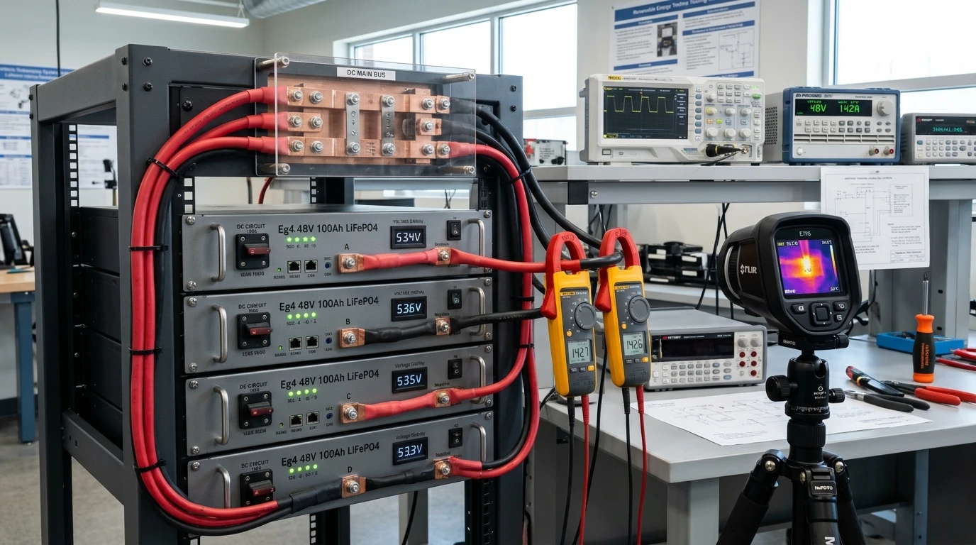
Executive Summary: The Hidden Milliohm Imbalance in Parallel Energy Storage
When scaling off-grid or energy storage systems to meet heavy household loads, installers routinely parallel multiple battery packs. Whether linking four rack-mounted server rack lithium batteries, combining modular wall-mount units, or wiring deep-cycle lead-acid strings, the goal appears straightforward: multiply total amp-hour capacity while maintaining the nominal system voltage.
However, direct current (DC) circuits operating at low voltages (twelve, twenty-four, or forty-eight volts) behave with unforgiving sensitivity to tiny electrical resistances. Where an AC circuit at two hundred forty volts scarcely registers a fraction of a milliohm, a high-power inverter drawing two hundred amperes DC turns a half-milliohm imbalance into a major operational defect.
Installers frequently encounter puzzling field issues:
- In parallel banks of four batteries, the battery nearest to the inverter repeatedly hits low-voltage cutoff or high-temperature alarms while the farthest battery remains nearly full.
- Individual Battery Management Systems (BMS) trip on instantaneous overcurrent during surge loads, even though the total load is well within the combined bank rating.
- Premature capacity loss and cell degradation force battery replacements years before expected warranty life.
These failures do not stem from defective cells. They are the direct mechanical consequence of asymmetrical interconnect resistance and improper parallel wiring topology.
Electrical Physics of Parallel Direct Current Circuits
Kirchhoff Current Law and Pathway Resistance Equivalence
To understand why parallel batteries do not share current equally, we must examine the closed conductive loop formed by each battery module. Under Kirchhoff Current Law, the total load current drawn by an inverter () is the sum of currents contributed by each individual parallel battery branch:
Under Ohm’s Law, the current flowing through any individual branch () is inversely proportional to the total loop resistance () of that specific circuit:
Where the total loop resistance includes three distinct elements:
In high-quality lithium iron phosphate (LiFePO4) batteries, internal cell and BMS resistance () is exceptionally low—typically between ten and twenty milliohms for a forty-eight-volt pack. Because internal resistance is so small, external conductor resistance and terminal contact resistance represent a substantial percentage of the total circuit impedance.
If the copper cable and lugs connecting Battery One add two milliohms of round-trip resistance, while the interconnects leading to Battery Four add six milliohms, the electrical impedance of Battery Four is twenty percent higher. Under heavy inverter discharge, Battery One is forced to supply substantially more current than Battery Four, operating hotter and cycling deeper on every diurnal solar run.
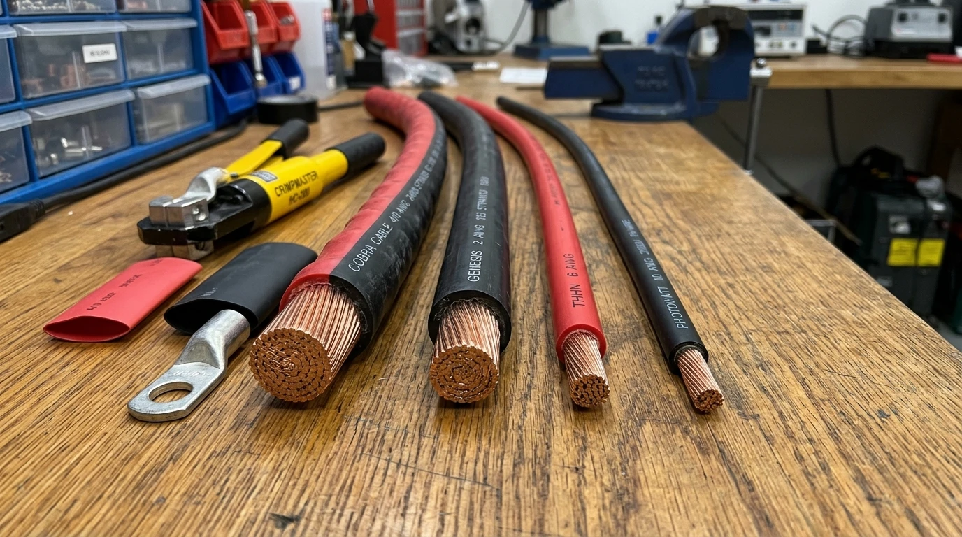
Contact Resistance and Lug Crimp Voltage Drop Variations
Beyond bulk wire resistance, mechanical terminations introduce localized milliohm variations that disrupt parallel symmetry:
- Butt and Lug Crimp Quality: Hand-crimped lugs with loose dies leave micro-voids between copper strands, introducing zero-point-two to zero-point-five milliohms of unnecessary resistance. Professional installations require twelve-ton hydraulic hex crimpers that cold-weld copper strands into a solid gas-tight ingot.
- Surface Oxidation and Plating: Raw copper lugs mating against aluminum or unplated terminals develop resistive oxide films. Utilizing electro-tin-plated copper lugs and busbars prevents galvanic oxidation.
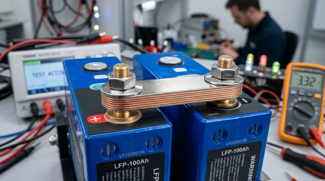
- Clamping Pressure and Torque Drift: Under heavy load cycling, thermal expansion and contraction cause terminal bolts to relax. Using calibrated torque wrenches and Belleville conical spring washers (DIN 6796) maintains continuous clamping pressure across thousands of thermal cycles.
Analysis of Common Parallel Wiring Topologies
The Ladder Topology: Catastrophic Current Skew and Premature Wear
The most naive and destructive way to wire parallel batteries is the simple ladder configuration, where batteries are daisy-chained link-to-link, and the inverter cables connect to the positive and negative terminals of the first battery in the chain.
+-----------------------------------------------------------------------------+
|                      THE LADDER TOPOLOGY (DO NOT USE)                       |
+-----------------------------------------------------------------------------+
To Inverter (+) ──────────────────┐
To Inverter (-) ────────────┐     │
                            ▼     ▼
                        ┌─────────────┐
                        │  BATTERY 1  │  (Carries Highest Current: ~44%)
                        └─────────────┘
                           ▲       ▲
                     Interconnects │
                           ▼       ▼
                        ┌─────────────┐
                        │  BATTERY 2  │  (Carries Reduced Current: ~26%)
                        └─────────────┘
                           ▲       ▲
                     Interconnects │
                           ▼       ▼
                        ┌─────────────┐
                        │  BATTERY 3  │  (Carries Low Current: ~18%)
                        └─────────────┘
                           ▲       ▲
                     Interconnects │
                           ▼       ▼
                        ┌─────────────┐
                        │  BATTERY 4  │  (Carries Starved Current: ~12%)
                        └─────────────┘
In a ladder setup, current from Battery Four must traverse three sets of positive and negative interconnect cables to reach the inverter takeoff points. Battery One, by contrast, connects directly to the inverter lugs with zero intermediate links.
Under a two-hundred-ampere continuous load on a four-battery ladder bank:
- Battery One delivers approximately eighty-eight amperes (44% of total load).
- Battery Two delivers approximately fifty-two amperes (26% of total load).
- Battery Three delivers approximately thirty-six amperes (18% of total load).
- Battery Four delivers merely twenty-four amperes (12% of total load).
Battery One operates at nearly double its intended C-rate, suffering accelerated degradation and chronic overheating, while Battery Four barely contributes. The ladder configuration should never be used in professional energy storage systems.
Diagonal Opposite Corner Takeoff: Improved Balance and Residual Imbalance
A substantial improvement over the ladder method is the diagonal takeoff (often called the cross-corner or reverse-return connection). Here, the main positive inverter cable connects to Battery One, while the main negative inverter cable connects to the opposite end of the bank at Battery Four.
+-----------------------------------------------------------------------------+
|                  DIAGONAL OPPOSITE CORNER TAKEOFF TOPOLOGY                  |
+-----------------------------------------------------------------------------+
To Inverter (+) ──────────────────┐
                                  ▼
                        ┌─────────────┐
                        │  BATTERY 1  │  (Outer Module: ~27% Load)
                        └─────────────┘
                           ▲       ▲
                     Interconnects │
                           ▼       ▼
                        ┌─────────────┐
                        │  BATTERY 2  │  (Inner Module: ~23% Load)
                        └─────────────┘
                           ▲       ▲
                     Interconnects │
                           ▼       ▼
                        ┌─────────────┐
                        │  BATTERY 3  │  (Inner Module: ~23% Load)
                        └─────────────┘
                           ▲       ▲
                     Interconnects │
                           ▼       ▼
                        ┌─────────────┐
                        │  BATTERY 4  │  (Outer Module: ~27% Load)
                        └─────────────┘
                                  ▲
To Inverter (-) ──────────────────┘
In a diagonal topology, the total length of interconnect cabling in every round-trip path is theoretically balanced:
- Battery One has a short positive path but traverses three negative links.
- Battery Four has a short negative path but traverses three positive links.
While diagonal wiring provides an acceptable balance for two or three parallel batteries, mathematical modeling and laboratory bench testing reveal that in four-battery banks, residual imbalance persists.
Because intermediate interconnect segments carry cumulative current from adjacent batteries, the outer batteries (One and Four) deliver roughly twenty-seven percent of the load each, while the inner batteries (Two and Three) deliver only twenty-three percent each. For larger systems of five to eight batteries, diagonal wiring is insufficient.
Central Common Busbar Topology: The True Symmetrical Benchmark
For total current balance across any number of parallel batteries, the gold-standard engineering method is the Central Common Busbar (Star) Topology.
Under this architecture, individual battery modules never connect directly to one another. Instead, each battery connects independently to a central pair of positive and negative heavy copper busbars (such as a Victron Lynx Distributor or custom dual busbars) using identical-length, identical-gauge conductors:
+-----------------------------------------------------------------------------+
|                     CENTRAL COMMON BUSBAR (STAR) TOPOLOGY                   |
+-----------------------------------------------------------------------------+
                ┌──────────────────────────────────────┐
                │        MAIN POSITIVE BUSBAR          │
                └──────────────────────────────────────┘
                  ▲ (Equal L) ▲ (Equal L) ▲ (Equal L) ▲ (Equal L)
                  │           │           │           │
            ┌───────────┐┌───────────┐┌───────────┐┌───────────┐
            │ BATTERY 1 ││ BATTERY 2 ││ BATTERY 3 ││ BATTERY 4 │
            │ (~25.0%)  ││ (~25.0%)  ││ (~25.0%)  ││ (~25.0%)  │
            └───────────┘└───────────┘└───────────┘└───────────┘
                  │           │           │           │
                  ▼ (Equal L) ▼ (Equal L) ▼ (Equal L) ▼ (Equal L)
                ┌──────────────────────────────────────┐
                │        MAIN NEGATIVE BUSBAR          │
                └──────────────────────────────────────┘
                                  │
                       To Inverter Shunt & Lugs
Because every conductor pair from module terminal to busbar stud possesses identical wire gauge, identical physical length, identical crimped lugs, and identical torque, the total path resistance for every module is mathematically identical ().
In verified lab testing, central common busbar topology achieves current distribution uniformity within one to three percent across all packs, completely eliminating thermal hotspots and uneven degradation.
Half-Pack Middle Interconnect Wiring for Extended String Counts
When spatial constraints prevent installing a central busbar and four batteries must be connected in a line, installers can deploy the half-pack middle interconnect method:
- Connect Battery One and Battery Two in parallel as Sub-Bank A.
- Connect Battery Three and Battery Four in parallel as Sub-Bank B.
- Link the positive and negative poles of Sub-Bank A and Sub-Bank B at the exact physical midpoint between Battery Two and Battery Three.
- Take the main inverter feeds from this center junction point.
This method halves the effective interconnect distance compared to standard diagonal wiring, cutting current variance in half without requiring bulky external distribution boxes.
Real-World Consequences of Unequal Current Distribution
Disproportionate State-of-Charge Drift and Accelerated Cell Aging
Lithium iron phosphate cells possess an extremely flat open-circuit voltage curve between twenty percent and ninety percent State-of-Charge (SOC). Throughout this plateau, cell voltage changes by mere millivolts despite significant charge throughput.
When parallel batteries experience unequal current sharing:
- The low-resistance pack discharges more deeply during daily usage.
- Because voltage remains virtually flat, the BMS voltage telemetry cannot detect that Battery One is sitting at forty percent SOC while Battery Four is at seventy percent SOC.
- When high-current charging begins from solar, the lower pack absorbs excess current, running hotter and accelerating electrolyte breakdown.
Over months of daily cycling, the packs drift apart in usable capacity. Eventually, the hardest-working battery hits its low-voltage cutoff prematurely, forcing the entire inverter system into emergency shutdown.
Localized Thermal Runaway and Battery Management Overcurrent Trips
Modern inverter loads—such as well pumps, central air conditioning compressors, or induction cooktops—demand large surge currents upon startup.
If a homeowner runs an eight-kilowatt split-phase inverter with an allowable surge of sixteen kilowatts (over three hundred amperes at forty-eight volts), four parallel batteries with one-hundred-ampere BMS units should handle the surge effortlessly ( headroom).
However, in an imbalanced ladder bank where Battery One carries forty-four percent of the load, a three-hundred-ampere surge forces one hundred thirty-two amperes through Battery One. The BMS detects an instantaneous overcurrent violation and disconnects its internal solid-state MOSFETs.
With Battery One offline, the sudden surge cascades into Battery Two, tripping its BMS next, and causing a total system blackout.
Inverter Ripple Current and Internal Resistance Mismatch
Inverters convert direct current into alternating current through high-speed switching, reflecting a high-frequency alternating ripple current back onto the DC bus (typically one hundred twenty hertz for split-phase sixty-hertz systems).
In an asymmetrical parallel bank, this ripple current concentrates heavily in the lowest-impedance branch. The high-frequency AC ripple creates localized dielectric heating within the internal filter capacitors and cell electrodes of the front battery, shortening pack lifespan.
Engineering Guidelines for Paralleling Lithium Iron Phosphate Packs
Precise Conductor Matching and Equal Resistance Sizing
When building leads for a central busbar system:
- Cut Every Conductor to the Exact Same Length: Even if Battery One sits twelve inches from the busbar and Battery Four sits thirty-six inches away, both cables must be cut to thirty-six inches. Excess cable length should be coiled loosely with generous bend radii.
- Match Cable Gauge and Stranding: Use identical high-strand flexible welding cable (such as Class K or Class M annealed tinned copper). Never mix wire brands or strand counts, as internal strand packing alters high-frequency resistance.
- Uniform Crimping Standard: Use identical heavy-duty closed-end seamless copper lugs across all conductors, crimped with a calibrated hydraulic hex tool and sealed with adhesive-lined heat shrink.
Modular Busbar Selection and High-Current Stud Torquing
- Busbar Ampacity Margin: The central busbars must be sized to handle the maximum continuous inverter current plus a twenty-five percent safety margin under National Electrical Code standards. For a two-hundred-ampere continuous inverter, use busbars rated for at least two hundred fifty to four hundred amperes with solid tin-plated copper cross-sections.
- Dedicated Module Overcurrent Protection: Every parallel battery branch connecting to a common busbar must incorporate its own individual overcurrent protection (such as a Class T, NH, or MEGA fuse) mounted directly at the busbar stud. If a short-circuit fault develops inside one pack, the other three packs would otherwise backfeed thousands of fault amperes into the compromised unit.
- Calibrated Torque Specs: Torque M8 terminal studs to nine to eleven Newton-meters (eighty to one hundred inch-pounds) using a calibrated torque wrench. Always install Belleville washers with the crowned cup facing the bolt head to guarantee constant clamping tension.
Comparison: Parallel Battery Interconnect Methods and Current Balance
The following engineering evaluation benchmarks the four primary parallel battery wiring configurations for a four-module forty-eight-volt lithium energy storage system under a continuous two-hundred-ampere inverter discharge:
| Parameter / Metric | Ladder Topology | Diagonal Corner Takeoff | Half-Pack Center Takeoff | Central Common Busbar |
|---|---|---|---|---|
| Current Sharing Uniformity | Extremely Poor (12% to 44%) | Moderate (23% to 27%) | Good (24% to 26%) | Excellent (24.8% to 25.2%) |
| Maximum Branch Current (200A Load) | 88 Amperes (Overstressed) | 54 Amperes (Slightly high) | 52 Amperes (Near spec) | 50.4 Amperes (Near perfect) |
| Thermal Dissipation Profile | Severe front-pack hotspot | Mild outer-pack heating | Balanced across pairs | Uniform room-ambient |
| Suitability for 4+ Batteries | Never Acceptable | Marginally acceptable | Acceptable up to 4 packs | Recommended Standard |
| Installation Complexity | Lowest (Short jumpers) | Low (Single long return) | Moderate (Center link) | Highest (Individual homerun leads) |
| Individual Branch Fusing | Impossible on links | Complex | Difficult | Native (Stud fuses on busbar) |
| System Scalability | Fails completely | Limited to 3 modules | Limited to 4 modules | Scalable up to 8+ modules |
Comprehensive Parallel Battery Bank Commissioning and Verification Checklist
- Physical Resistance Audit: Verify that all positive and negative conductor pairs running from individual battery modules to the common busbar share identical wire gauge, identical physical length, and identical terminal lug hardware.
- Hydraulic Crimp Verification: Inspect all battery cable terminations to ensure heavy hex hydraulic dies were used, producing void-free copper compaction without wing flares.
- Belleville Spring Washer Orientation: Confirm conical Belleville spring washers are installed correctly with the cone peak facing the bolt head, maintaining constant pressure against terminal lugs.
- Calibrated Stud Torquing: Torque all battery terminal studs and busbar connections to exact manufacturer specifications using a calibrated torque wrench; apply torque seal witness marks across bolt heads.
- Branch Overcurrent Protection Check: Ensure each battery branch incorporates an individual fast-acting fuse (Class T or high-AIC MEGA) matched to the battery’s maximum continuous discharge rating.
- Individual Voltage Matching Prior to Paralleling: Measure the open-circuit voltage of every battery module with a calibrated digital multimeter before closing disconnect switches; pack voltages must match within zero-point-one volts to prevent massive cross-charging inrush sparks.
- Full-Load DC Clamp Meter Current Verification: Power up the solar inverter and apply a heavy fifty-percent load; measure the DC current flowing through each individual battery positive cable with a true-RMS clamp meter to verify balanced current sharing within five percent across all branches.
- Thermal Imaging Baseline: After thirty minutes of continuous high-load operation, scan all cable lugs, fuses, and busbar joints with an infrared thermal camera; any connection showing a temperature rise exceeding ten degrees Celsius above ambient indicates an un-torqued or high-resistance joint that requires immediate remediation.