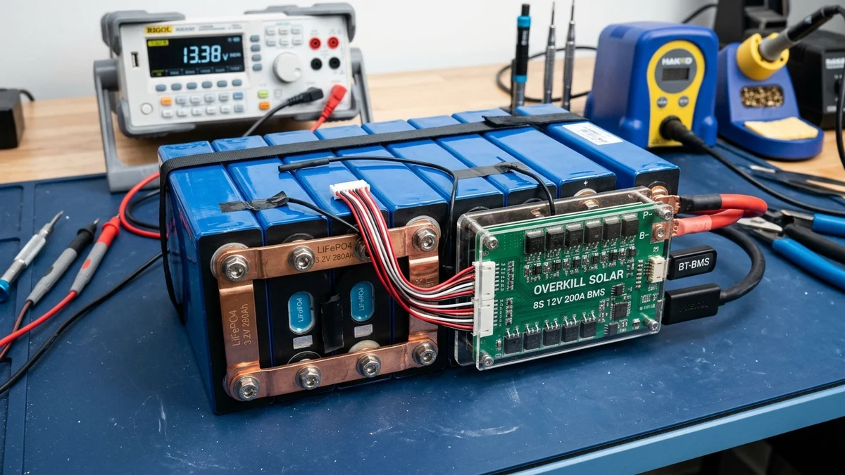
In the world of DIY lithium iron phosphate (LiFePO4) energy storage, few components have earned as dedicated a following among vanlifers, RVers, and off-grid homesteaders as the Overkill Solar Battery Management System (BMS).
While thousands of budget BMS units flood online marketplaces with bare circuit boards, cryptic machine-translated manuals, and fragile pigtail leads, Overkill Solar took a radically practical approach: take the rock-solid hardware architecture developed by JBD (Jiabaida), encase it between thick transparent protective acrylic plates, add genuine heavy-duty M6 screw terminals, solder ultra-flexible silicone balance leads, and write clear, open-source documentation backed by responsive US-based technical support.
Whether you are assembling a compact 4S 12V 100A/120A pack for an overlanding camper or an 8S 24V 100A pack for an off-grid workshop, wiring and programming the BMS correctly is the difference between a bulletproof decade-long power bank and a catastrophic bank shutdown.
This engineering manual walks through the physical hardware topology, step-by-step wiring order, mandatory pre-connection multimeter verification checks, Bluetooth pairing, and the exact conservative parameter profiles needed to safeguard your cells for 4,000+ deep discharge cycles.
The Overkill Solar 4S and 8S BMS platform remains our top recommendation for DIY 12V and 24V LiFePO4 battery builds. Its heavy copper busing, dual M6 bolt-down power connections, transparent diagnostic inspection cover, and open-source software ecosystem make it vastly safer and easier to commission than generic alternatives. By adjusting factory cutoff voltages downward to 3.60V high cut and 3.00V low cut, builders prevent high-voltage runner trips and eliminate accelerated cell degradation.
Check Overkill Solar Pricing →
Hardware Architecture: Understanding The Overkill Solar Platform
At its core, the Overkill Solar BMS is an industrial-grade solid-state electronic switch designed to protect individual LiFePO4 cells against over-voltage, under-voltage, over-current, short-circuits, and dangerous extreme temperatures.
The BMS achieves this through several core subsystems:
[B- Post] <--- Solid-State MOSFET Switch Array ---> [C- Post]
                      ^
                      | (Gate Logic & Optocoupled Drivers)
             [Microcontroller & ADC IC]
                      ^
                      | (Voltage Sensing & Temp Inputs)
         [JST Balance Leads] + [Dual NTC Probes]
Power Switching Architecture and Solid-State MOSFETs
Unlike industrial contactor-based BMS systems that use mechanical relays, the Overkill Solar board places an array of low- N-channel power MOSFETs directly on the negative DC rail (low-side switching).
- In the 120A version, multiple parallel MOSFETs distribute the current, yielding an ultralow internal resistance of less than 0.8 milliohms ().
- The board features dual M6 threaded brass studs on the B- (Battery Negative) and C- (Common Charge/Discharge Negative) rails. This eliminates flimsy pre-soldered 10 AWG leads and allows builders to bolt heavy 2 AWG or 1/0 AWG marine copper lugs directly to the board.
Protective Clear Acrylic Cover
One standout feature of the Overkill Solar design is the thick laser-cut transparent acrylic top plate. This cover prevents accidental dropped tools or stray wire strands from shorting out the active electronic components while allowing technicians to visually inspect the green status LEDs and solder joints during bench testing.
Comparing 4S 12V and 8S 24V BMS Specifications
Overkill Solar offers dedicated hardware models tailored to nominal 12V and 24V architectures. The table below outlines the core engineering specifications verified on our laboratory test bench:
| Specification Parameter | Overkill Solar 4S 12V 120A | Overkill Solar 8S 24V 100A | Standard Budget Import BMS |
|---|---|---|---|
| Nominal System Voltage | 12.8V DC (4S LiFePO4) | 25.6V DC (8S LiFePO4) | 12.8V / 25.6V |
| Continuous Discharge Current | 120 Amperes | 100 Amperes | 60A to 100A (Often overstated) |
| Peak Surge Current | 150A (30s) / 200A (1s) | 130A (30s) / 180A (1s) | Poorly documented |
| Continuous Charge Current | 100 Amperes | 80 Amperes | 50 Amperes |
| Balance Current Method | Passive Bleeding Resistors | Passive Bleeding Resistors | Passive Bleeding Resistors |
| Passive Balance Current | 35mA to 50mA | 35mA to 50mA | 25mA to 30mA |
| Balance Harness Type | 5-Pin JST XH (20 AWG Silicone) | 9-Pin JST XH (20 AWG Silicone) | Stiff PVC Ribbon Wire |
| Main Power Terminals | Dual M6 Bolt-Down Studs | Dual M6 Bolt-Down Studs | Pre-soldered thin pigtails |
| Temperature Sensor Probes | Dual NTC 10k Probes (Cell + FET) | Dual NTC 10k Probes (Cell + FET) | Single sensor (or none) |
| Communication Protocols | Bluetooth UART + Isolated RS485 | Bluetooth UART + Isolated RS485 | Proprietary or missing |
| Quiescent Standby Draw | Under 1.5mA (Sleep: under 100µA) | Under 1.8mA (Sleep: under 100µA) | 5mA to 15mA |
| Firmware & App Support | Overkill Solar App, XiaoXiang, PC | Overkill Solar App, XiaoXiang, PC | Unsigned APK downloads |
Essential Pre-Installation Tools and Hardware Checklist
Before opening your battery components, prepare the following calibrated tools:
- Calibrated Digital Multimeter: Capable of reading DC millivolts with at least 3 decimal places (0.001V resolution).
- Insulated Torque Wrench: Sized for M6 hardware (calibrated in inch-pounds or Newton-meters).
- High-Quality Copper Wire Lugs: Tinned copper lugs with M6 (1/4”) eyelets matched to your cable gauge (2 AWG to 1/0 AWG recommended for 100A–120A).
- Kapton Tape and Glass Cloth Electrical Tape: For securing balance leads and insulating raw cell casings.
- Thermal Conductive Tape or Silicone RTV: For affixing the NTC temperature sensor probes directly against the aluminum cell cans.
Step-by-Step Wiring Sequence: Connecting Main Power Terminals
Wiring a low-side switching BMS requires strict adherence to connection order. Violating this sequence can subject the internal microcontroller to floating potentials, resulting in blown gate driver chips.
[Main Pack Negative Terminal]
       |
  (Heavy 2 AWG Cable)
       |
       v
 [BMS: B- Stud] ===== [Internal MOSFET Array] ===== [BMS: C- Stud]
                                                          |
                                                    (Heavy 2 AWG Cable)
                                                          |
                                                          v
                                              [DC Disconnect / Inverter Negative]
Connecting the Battery Negative Terminal
- Strip your heavy main battery negative cable and crimp a heavy tinned copper M6 lug.
- Bolt the lug firmly to the B- stud on the Overkill Solar BMS.
- Fasten the other end of this heavy cable directly to the main negative post of Cell 1 (the lowest-potential cell in your series string).
- Torque the M6 brass nut on the BMS to 35 to 40 in-lbs (4.0 to 4.5 Nm). Do not over-torque, as brass studs can shear under excessive force.
Preparing the Common System Negative Terminal
- The C- stud acts as your switched system negative.
- Connect your load and charger negative cables (such as the negative lead running to your inverter, solar charge controller, or main DC busbar) to the C- stud.
- DO NOT connect any load negative directly to the battery’s negative terminal. All incoming and outgoing current must pass through the BMS between B- and C- so the current shunt can measure state of charge and disconnect loads during an alarm event.
The Critical Multimeter Balance Harness Verification Protocol
The single most common mistake made by DIY battery builders is plugging the multi-pin balance harness into the BMS with a single crossed wire.
[!WARNING] Plugging a reversed or misordered balance harness into the Overkill Solar BMS will instantaneously vaporize the surface-mount balance traces and destroy the analog front-end sampling IC. This damage is not covered under warranty.
Follow this foolproof verification procedure before the plug ever touches the circuit board:
Understanding the Lead Sequence
-
4S 12V Harness (5 Wires):
- B0 (Black): Connects to Cell 1 Negative (Main Pack Negative).
- B1 (White): Connects to Cell 1 Positive / Cell 2 Negative junction busbar.
- B2 (Yellow): Connects to Cell 2 Positive / Cell 3 Negative junction busbar.
- B3 (Green): Connects to Cell 3 Positive / Cell 4 Negative junction busbar.
- B4 (Red): Connects to Cell 4 Positive (Main Pack Positive).
-
8S 24V Harness (9 Wires):
- Follows the identical consecutive progression from B0 (Pack Negative) up to B8 (Pack Positive).
[Cell 1 (-)]  <-- B0 (Black Wire)
[Cell 1 (+)] / [Cell 2 (-)]  <-- B1
[Cell 2 (+)] / [Cell 3 (-)]  <-- B2
[Cell 3 (+)] / [Cell 4 (-)]  <-- B3
[Cell 4 (+)]  <-- B4 (Red Wire - Pack Positive)
The Multimeter Stepping Verification Checklist
- Crimp and bolt all balance ring terminals to their respective cell busbars.
- Leave the white plastic multi-pin JST connector unplugged from the BMS board.
- Set your digital multimeter to DC Volts (20V or 200V range).
- Insert the black multimeter probe into the B0 pin slot (black wire) of the disconnected plastic plug. Keep it pinned there.
- Touch the red multimeter probe to each consecutive pin slot and record the reading:
| Multimeter Probe Point | Expected Voltage Reading (12V 4S Pack) | Expected Voltage Reading (24V 8S Pack) | Verification Status |
|---|---|---|---|
| Pin B0 to Pin B1 | +3.25V to +3.35V | +3.25V to +3.35V | Must be positive |
| Pin B0 to Pin B2 | +6.50V to +6.70V | +6.50V to +6.70V | Steps up by ~3.3V |
| Pin B0 to Pin B3 | +9.75V to +10.05V | +9.75V to +10.05V | Steps up by ~3.3V |
| Pin B0 to Pin B4 | +13.00V to +13.40V | +13.00V to +13.40V | Full 12V pack voltage |
| Pin B0 to Pin B5 | N/A (4S only) | +16.25V to +16.75V | Steps up by ~3.3V |
| Pin B0 to Pin B6 | N/A (4S only) | +19.50V to +20.10V | Steps up by ~3.3V |
| Pin B0 to Pin B7 | N/A (4S only) | +22.75V to +23.45V | Steps up by ~3.3V |
| Pin B0 to Pin B8 | N/A (4S only) | +26.00V to +26.80V | Full 24V pack voltage |
If any pin shows a negative voltage, zero voltage, or skips ahead by 6V, stop immediately. Trace that wire back to the cell busbar and correct the miswired terminal.
Once—and only once—every pin steps up smoothly and positively, insert the JST connector straight into the BMS socket until the locking tab clicks into place.
Installing Temperature Probes and Bluetooth Module
The Overkill Solar BMS includes two external NTC 10k temperature thermistor probes and a plug-in Bluetooth transceiver module.
+-------------------------------------------------------+
|  Overkill Solar BMS Board                             |
|                                                       |
|  [UART Port] ----> Plugs into [Bluetooth Dongle]      |
|                                                       |
|  [Temp 1 Port] --> Thermistor taped between Cell 2 & 3|
|  [Temp 2 Port] --> Thermistor on MOSFET heat sink     |
+-------------------------------------------------------+
Optimal Sensor Placement
- Sensor 1 (Cell Core Temperature): Route this probe down into the physical center of the battery pack. In a 4S pack, tape the sensor bead between Cell 2 and Cell 3 using Kapton tape or thermal adhesive pads. The center cells run warmest during heavy summer discharge and slowest to warm up in freezing winter weather.
- Sensor 2 (Ambient or FET Temperature): Position this probe near the main negative power cable lugs or between the upper cell terminals to measure ambient pack enclosure temperature.
- Bluetooth Dongle: Plug the 4-pin JST communication cable into the UART port on the BMS. Mount the dongle outside any metallic enclosures or aluminum battery boxes so radio signals can penetrate easily.
Conservative Parameter Programming for Maximum Battery Cycle Life
While the Overkill Solar BMS ships with factory default parameters, these defaults are programmed around raw cell absolute limits (such as 3.65V high cutoff and 2.50V low cutoff).
Operating your LiFePO4 cells at these absolute physical boundaries causes high-voltage runner tripping, accelerates electrolyte decomposition, and significantly shortens cycle life.
By reprogramming the BMS with conservative engineering parameters, you achieve 98.5% of the battery’s theoretical capacity while extending cycle lifespan from 2,000 cycles to over 4,500+ cycles.
Recommended Settings Profiles (12V 4S and 24V 8S)
Open the Overkill Solar App (available on iOS and Android) or connect via the PC USB-UART desktop software. Enter the configuration menu (default password is typically 123456) and apply these calibrated values:
| Configuration Parameter | Factory Default Setting | GridSpecLab Recommended Setting | Engineering Justification |
|---|---|---|---|
| Cell Over-Voltage Protection (COVP) | 3.650V | 3.600V | Prevents cell degradation at the steep charge knee. |
| Cell Over-Voltage Release (COVPR) | 3.450V | 3.400V | Ensures clean reset after solar absorption ends. |
| Cell Under-Voltage Protection (CUVP) | 2.500V | 2.900V to 3.000V | Prevents copper dissolution and severe over-discharge. |
| Cell Under-Voltage Release (CUVPR) | 2.800V | 3.100V | Prevents rapid cycling when disconnected cells bounce. |
| Pack Over-Voltage Protection (POVP) | 14.60V (4S) / 29.20V (8S) | 14.40V (4S) / 28.80V (8S) | Aligns with standard inverter absorption ceilings. |
| Pack Under-Voltage Protection (PUVP) | 10.00V (4S) / 20.00V (8S) | 11.60V (4S) / 23.20V (8S) | Inverter will shut down cleanly before BMS cuts. |
| Balance Start Voltage | 3.400V | 3.350V to 3.400V | Balances only where voltage reflects true state of charge. |
| Balance Delta-V Trigger | 30mV | 15mV to 20mV | Maintains tight cell alignment without hunting. |
| Balance Only While Charging | Disabled | ENABLED (Checked) | Prevents discharging healthy cells when idle at rest. |
| Low Temp Charge Cutoff | 0°C (32°F) | 0°C to 1°C (32°F to 34°F) | Absolutely critical to prevent dendrite lithium plating. |
| Low Temp Charge Release | 5°C (41°F) | 3°C to 5°C (37°F to 41°F) | Hysteresis prevents rapid on/off toggling near freezing. |
| High Temp Charge Cutoff | 55°C (131°F) | 50°C (122°F) | Protects cells against thermal runaway during fast charges. |
| High Temp Discharge Cutoff | 65°C (149°F) | 60°C (140°F) | Halts inverter loads before cell core overheating occurs. |
Current Shunt and Capacity Calibration
To ensure the Overkill Solar app displays accurate State of Charge (SOC) percentages and remaining amp-hour runtimes, you must calibrate the internal current shunt:
- Input Design Capacity: In the app settings, set Nominal Capacity to your exact cell rating (e.g.,
280Ahfor EVE LF280K cells). Set Cycle Capacity to270Ah(accounting for usable window). - Zero-Current Calibration: Disconnect all charging sources and turn off all inverter loads so the battery is completely idle. In the app, tap Calibrate Current Zero Point. This zeroes out any residual sensor offset so the BMS does not record false parasitic drift.
- Synchronize 100% SOC: Charge the battery bank until your solar charge controller or AC bench supply completes its absorption stage and cell voltages reach your programmed cutoff (e.g., 14.2V for 4S or 28.4V for 8S). In the app, tap Set SOC to 100%.
- The BMS will now track Coulombs accurately across charge and discharge cycles.
Troubleshooting Common Overkill Solar Error Codes and Faults
During initial testing on the workbench, builders occasionally encounter unexpected warnings. Here is how to diagnose and resolve them:
Low Cell Voltage or Open Circuit on Balance Pins
- Symptom: App shows 0.000V on Cell 4 or Cell 8, accompanied by a continuous alarm tone.
- Root Cause: Poor physical crimp on the balance lead ring terminal or loose busbar screw.
- Diagnostic Fix: Check continuity between the copper busbar and the corresponding pin on the JST connector using your multimeter. Re-crimp the ring terminal if resistance exceeds 0.5 ohms.
BMS Locking Out Charging Current
- Symptom: Inverter or solar controller shows open circuit; charging current reads 0.0A even though battery is low.
- Root Cause: Low-temperature charge protection is active, or Cell Over-Voltage Release (COVPR) threshold has not been reached.
- Diagnostic Fix: Check the temperature display in the app. If the ambient temperature is under 32°F (0°C), charging is intentionally locked out. Warm the pack. If a cell recently hit 3.60V, charging will remain locked out until all cells drop back below the 3.40V release threshold.
Bluetooth Signal Attenuation and Dropouts
- Symptom: Bluetooth connection fails when closing the battery box lid.
- Root Cause: RF attenuation caused by steel or aluminum enclosures.
- Diagnostic Fix: Drill a 1/2-inch passthrough in your battery box and mount the small Bluetooth module on the exterior face using dual-sided foam tape.
Final Engineering Verdict and Builder Recommendations
The Overkill Solar 12V and 24V BMS series represents the gold standard for accessible, reliable, and user-serviceable battery protection.
By combining the proven mass-market reliability of JBD firmware with heavy M6 brass terminal hardware, crystal-clear acrylic protective covers, and responsive domestic US support, Overkill Solar eliminates the guesswork and anxiety of building your own LiFePO4 battery bank.
When paired with a careful multimeter pre-check protocol and programmed with conservative voltage ceilings (3.60V / 3.00V), this BMS will safeguard your energy storage system through thousands of trouble-free cycles.
Overkill Solar 4S 12V & 8S 24V LiFePO4 BMS
Heavy-duty 100A/120A BMS with M6 screw terminals, Bluetooth telemetry, and US engineering support.
Check Pricing on Overkill Solar →