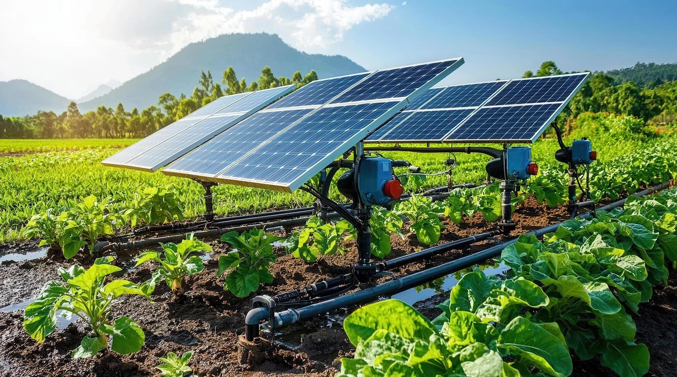
Delivering reliable, automated irrigation to homestead gardens, off-grid orchards, or remote high-tunnel greenhouses presents a classic hydraulic and electrical engineering challenge.
Unlike grid-tied municipal systems that provide continuous 50 to 60 PSI city water pressure, an off-grid solar irrigation system must independently generate its own hydraulic head from shallow wells, rainwater catchment cisterns, or farm ponds using direct-current (DC) power.
For low-volume drip irrigation, homesteaders routinely select 12-volt or 24-volt positive displacement diaphragm pumps (such as industrial units manufactured by Shurflo, Seaflo, or Remco). These pumps are self-priming, can safely run dry without immediate catastrophic failure, and generate substantial delivery pressures ranging from 45 to 60 PSI.
However, pairing a positive displacement diaphragm pump with micro-irrigation drip tape introduces a critical mechanical failure mode: destructive pressure switch rapid cycling.
In this comprehensive engineering sizing guide, GridSpecLab details the exact physics of emitter water demand calculations, examines internal bypass versus mechanical pressure switch dynamics, provides mathematical formulas for sizing accumulator tanks, and outlines electrical buffering with LiFePO4 batteries and DC latching solenoids.
Never connect a positive displacement diaphragm pump directly to a drip irrigation line without an accumulator tank and an inline pressure regulator. A drip manifold demanding 0.8 GPM from a 4.0 GPM pump forces the pressure switch to chatter on and off every 0.3 seconds. Adding a 2-gallon bladder tank pre-charged to 28 PSI dampens cycle frequency, extends switch contact lifespan tenfold, and preserves consistent emitter discharge.
Calculating Irrigation Water Demands and Operating Pressure
Before purchasing a single fitting, pump, or solar panel, you must calculate the total volumetric water requirement and hydraulic pressure profile of your target irrigation zones.
Drip irrigation components are engineered to deliver precise volumes of water directly to plant root zones, minimizing evaporative losses. However, unlike high-flow impact sprinklers or overhead rotors that consume multiple gallons per minute (GPM), individual drip emitters operate on tiny fractions of Gallons Per Hour (GPH).
Emitter Flow Rate Aggregation
To establish the total flow rate required from your pump, sum the rated discharge of every active emitter across your largest single irrigation zone:
Total Zone Flow (GPH) = Emitter Count × Rated Emitter Flow (GPH)
Total Zone Flow (GPM) = Total Zone Flow (GPH) / 60
Consider a homestead vegetable patch featuring five 100-foot raised beds. If each bed contains two runs of 1/2-inch drip tubing with pressure-compensating 1.0 GPH emitters spaced every 12 inches:
- Total emitters per bed:
200 emitters - Total emitters across five beds:
1,000 emitters - Total zone flow in GPH:
1,000 × 1.0 GPH = 1,000 GPH - Total zone flow in GPM:
1,000 / 60 = 16.67 GPM
In this high-capacity scenario, running all beds simultaneously demands 16.7 GPM, which exceeds the throughput capacity of standard compact 12V diaphragm pumps (which peak around 3.0 to 5.5 GPM). The correct engineering solution is subdividing the layout into multiple zones controlled by automated solenoid valves.
If the 1,000-emitter field is split into four distinct zones of 250 emitters each:
Single Zone Flow (GPH) = 250 × 1.0 GPH = 250 GPH
Single Zone Flow (GPM) = 250 / 60 = 4.17 GPM
A flow demand of 4.17 GPM matches the sweet spot of a commercial 5.0 GPM 12V or 24V diaphragm pump.
Operating Pressure Requirements: Drip Tape vs Pressure-Compensating Tubing
Different micro-irrigation emitters operate within strict hydraulic pressure bands:
| Irrigation Emitter Type | Nominal Pressure Window | Burst / Disconnect Risk | Required Flow Regulation |
|---|---|---|---|
| Thin-Wall Drip Tape (8–15 mil) | 8 to 15 PSI | Above 25 PSI (Blowouts common) | 10–15 PSI preset regulator |
| Heavy-Wall Drip Tubing (1/2” PE) | 15 to 30 PSI | Above 45 PSI (Fitting pop-offs) | 20–25 PSI preset regulator |
| Pressure-Compensating (PC) Emitters | 15 to 45 PSI | Above 55 PSI (Internal diaphragm slip) | 25–30 PSI preset regulator |
| Micro-Sprays & Landscape Bubblers | 20 to 40 PSI | Above 50 PSI (Misting and drift) | 30 PSI preset regulator |
Because standard DC diaphragm pumps feature factory mechanical pressure switches configured to shut off at 45 to 60 PSI, routing pump discharge directly into thin-wall drip tape without a pressure-reducing regulator will rupture the tape or blow compression barbed fittings off lateral lines.
An inline preset pressure regulator (20 or 25 PSI) installed downstream of the pump and filter manifold is mandatory.
Positive Displacement Diaphragm Pump Mechanics
Understanding how a DC diaphragm pump operates reveals why micro-irrigation requires specialized plumbing protections.
Unlike centrifugal well pumps or circulating impeller pumps that modulate flow based on backpressure, a diaphragm pump is a positive displacement machine. An electric permanent-magnet DC motor rotates an eccentric wobble plate, driving three, four, or five flexible rubber diaphragms back and forth inside sealed chambers equipped with one-way check valves.
       [Electric DC Motor]
               │
      [Eccentric Cam / Swashplate]
               │
    ┌──────────┼──────────┐
 [Chamber A] [Chamber B] [Chamber C]
    │          │          │
    └──────────┬──────────┘
               ▼
   [Discharge Manifold & Check Valves]
               │
    [Mechanical Pressure Switch] ────► Breaks Motor Circuit at 55 PSI
Each stroke of a chamber displaces a fixed, incompressible volume of water. If the discharge line is open, fluid flows continuously. If flow is restricted, pressure inside the discharge manifold climbs almost instantaneously until the pump’s integrated mechanical pressure switch activates, opening its electrical contacts and killing power to the motor.
The Rapid Cycling Trap: Switch Chatter and Contact Burnout
When a pump rated for 5.0 GPM feeds an open garden hose flowing at 4.5 GPM, the pump runs smoothly and continuously because discharge demand nearly balances pump output.
However, when that same 5.0 GPM pump is connected to an orchard zone demanding only 1.2 GPM:
- The pump produces water four times faster than the drip emitters can release it.
- Pressure inside the rigid plumbing spikes from 35 PSI to 55 PSI in less than 200 milliseconds.
- The mechanical pressure switch cuts motor power at 55 PSI.
- The drip emitters bleed off water, causing line pressure to drop back down to the 35 PSI cut-in threshold within another 200 milliseconds.
- The switch snaps closed, re-energizing the motor.
This violent cycle repeats at 2 to 4 cycles per second (switch chatter).
Within minutes of switch chatter, internal electrical arcing overheats the contact points, causing contact pitting, mechanical fatigue, or complete contact welding. Simultaneously, the motor experiences severe inrush current surges, driving operating temperatures past thermal insulation ratings.
Internal Bypass Valves: Operating Characteristics and Limitations
Some modern DC pumps (such as Shurflo 4008 or Seaflo 42 Series) incorporate an internal bypass valve alongside or in place of the mechanical pressure switch.
An internal bypass consists of a spring-loaded diaphragm that allows excess pressurized water to recirculate from the high-pressure discharge port back into the low-pressure suction chamber within the pump head itself.
While bypass pumps reduce pressure switch chatter during moderate flow restrictions, they present two notable limitations for off-grid homesteaders:
- Recirculating water through a constricted internal port generates continuous fluid friction, warming the pump head and wasting valuable solar battery watt-hours.
- If zone demand drops below 0.5 GPM, even internal bypass mechanisms experience hunting and erratic delivery pressure.
The ultimate engineering defense against rapid cycling is not relying on bypass valves alone, but incorporating a hydronic storage vessel: an accumulator tank.
Adding an Accumulator Tank to Prevent Pressure Switch Flutter
An accumulator tank (frequently called an expansion bladder tank) is an essential component for any off-grid diaphragm pump installation.
       [DC Diaphragm Pump]
               │
               ├──► [Accumulator Bladder Tank (0.5 – 2.0 Gal)]
               │        (Pre-charged with air to Cut-In - 3 PSI)
               ▼
     [120-Mesh Disc Filter]
               │
    [25 PSI Pressure Regulator]
               │
   [Automated Latching Solenoids]
               │
    [Drip Lateral Lines & Emitters]
Physics of Hydronic Bladder Dampening
An accumulator tank features a steel or composite pressure vessel divided into two chambers by a flexible butyl rubber bladder:
- One chamber is connected directly to the water distribution plumbing.
- The opposite chamber contains pressurized atmospheric air charged through a standard Schrader valve.
Because air is highly compressible while water is virtually incompressible, water pumped into the accumulator compresses the captive air pocket. When the pump turns off, the expanding air cushion forces water back into the drip line, maintaining pressure without requiring the pump motor to restart immediately.
Sizing Accumulator Tank Volume
Accumulator tanks for off-grid solar systems typically range in capacity from 0.5 gallons (2.0 liters) to 2.0 gallons (8.0 liters):
- Small Homestead Zones (Flow demand 0.5 to 1.5 GPM): A 0.5-gallon accumulator provides sufficient volume to stretch pump cycle intervals from fractions of a second to 15–20 seconds of sustained run time followed by 30–45 seconds of resting time.
- Large Homestead Zones (Flow demand 1.5 to 4.0 GPM): A 2.0-gallon accumulator stores approximately 0.7 to 0.9 gallons of usable drawdown water between 35 PSI cut-in and 55 PSI cut-out, ensuring deep, healthy pump run cycles.
Bladder Air Pre-Charge Pressure Calibration
A common installation error is connecting an accumulator tank straight out of the box without verifying or tuning its factory air pre-charge pressure.
To properly calibrate an accumulator tank:
Target Air Pre-Charge Pressure = Pump Mechanical Cut-In Pressure - (2 to 3 PSI)If your pump is rated with a 35 PSI cut-in and 55 PSI cut-out:
- Disconnect the pump from power and open an downstream irrigation valve so line water pressure drops to exactly 0 PSI.
- Measure the accumulator Schrader valve pressure using a precision tire gauge.
- Adjust air pressure using a bicycle hand pump to exactly 32 to 33 PSI (2 to 3 PSI below cut-in).
If the air pre-charge is set higher than the pump cut-in pressure (e.g., 38 PSI), the bladder remains completely collapsed against the inlet until pressure exceeds 38 PSI, severely reducing usable drawdown volume.
Conversely, if pre-charge pressure is too low (e.g., 15 PSI), line pressure will compress the bladder almost completely flat against the tank walls, leaving zero air cushion to dampen pressure spikes.
Sizing Direct Current Battery Buffers and Interval Timers
Operating a diaphragm pump directly from a photovoltaic (PV) solar panel without an electrical energy buffer is notoriously unreliable: solar irradiance fluctuates with every passing cloud, causing pump motor voltage to sag, stalling the pump against head pressure, and triggering motor thermal overload trips.
A properly engineered off-grid irrigation station combines a dedicated LiFePO4 battery buffer, an MPPT or PWM solar charge controller, and an energy-efficient DC irrigation timer.
Direct Current Voltage Selection: Twelve-Volt vs Twenty-Four-Volt Architecture
Choosing between 12V and 24V DC operating voltage depends primarily on wiring distance:
Ohm's Law & Conductor Sizing:
Current (Amperes) = Power (Watts) / Voltage (Volts)
Resistive Voltage Drop (Volts) = 2 × Length (ft) × Current (Amps) × Conductor Resistance / 1,000
A standard 5.0 GPM, 55 PSI diaphragm pump consumes approximately 100 to 120 Watts under full load:
- At 12V DC, the pump draws 8.5 to 10.0 Amperes continuous, with starting inrush surges reaching 15 Amperes.
- At 24V DC, the pump draws only 4.2 to 5.0 Amperes continuous, with starting surges contained below 8 Amperes.
If your pump station is located 50 feet away from the battery bank (100 feet round-trip conductor length):
- A 12V system requires heavy 6 AWG copper wire to keep voltage drop under 3% (0.36V drop).
- A 24V system requires only 12 AWG copper wire to achieve the same 3% threshold (0.72V drop).
For any system where electrical cable runs exceed 25 feet, or where daily irrigation demands exceed 2 hours of continuous run time, 24V DC architecture is vastly superior.
Battery Storage and Solar Panel Sizing Calculation
Consider a 24V irrigation station powering a 4.5 GPM pump running two 45-minute watering cycles per day (1.5 hours total runtime):
Daily Energy Consumption:
Pumping Load = 120 Watts × 1.5 Hours = 180 Watt-Hours (Wh)
Controller / Timer Idle Load = 2 Watts × 24 Hours = 48 Wh
Total Daily Consumption = 180 + 48 = 228 Wh / Day
Factoring in wiring losses and battery round-trip efficiency (92% for LiFePO4):
Required Daily Solar Generation = 228 Wh / 0.90 = 253 WhAssuming a conservative winter solar window of 3.5 Peak Sun Hours (PSH):
Required Solar PV Array = 253 Wh / 3.5 PSH = 72.3 WattsTo provide guaranteed operation during three consecutive overcast rainy days (autonomy):
Battery Capacity Required = (228 Wh × 3 Days Autonomy) / (25.6V Nominal × 0.80 Max DoD)
Battery Capacity Required = 684 Wh / 20.48V = 33.4 Amp-Hours (Ah) at 24V
Recommended Homestead Sizing Specification:
- Solar PV Panel: Single 100W or 150W monocrystalline panel.
- Charge Controller: 10A or 15A Victron Energy SmartSolar MPPT 75/15.
- Battery Storage: 24V 30Ah LiFePO4 pack (or two 12V 50Ah LiFePO4 batteries in series).
Automated Control: Direct Current Latching Solenoid Valves
Standard residential irrigation valves utilize 24V Alternating Current (AC) solenoids that require continuous AC power (approximately 0.2 to 0.4 Amperes at 24VAC) to hold the internal valve plunger open. Running an inverter 24/7 to power AC solenoids wastes significant battery energy through inverter standby tare loss (typically 15 to 30 Watts continuous, or 360 to 720 Wh/day—triple the pump consumption!).
The professional off-grid solution is utilizing 9V/12V DC Latching Solenoids (manufactured by Hunter, Rain Bird, or DIG):
- A DC latching solenoid requires a momentary 50-millisecond pulse of direct current to mechanically snap the magnetic plunger into the OPEN position.
- Zero power is consumed while the valve remains open.
- When the watering cycle completes, the controller sends an opposite polarity 50-millisecond pulse to snap the plunger CLOSED.
Pairing DC latching solenoids with battery-operated solid-state node controllers (such as the Hunter Node or Rain Bird WPX series) eliminates standby power drain entirely.
Filtration Requirements: Preventing Emitter Clogging
Micro-irrigation emitters feature microscopic water exit pathways ranging from 0.020 inches to 0.045 inches (0.5 to 1.1 mm) in diameter. Without robust filtration, suspended sediment, algae filaments, and mineral precipitates will permanently clog emitters within weeks of operation.
Because diaphragm pump valves are also susceptible to grit damage, filtration must be implemented at two strategic locations in the system:
[Water Tank / Pond] ──► [50-Mesh Suction Strainer] ──► [Diaphragm Pump] ──► [120-Mesh Disc Filter] ──► [Drip Manifold]Pre-Pump Suction Strainer (Protection for Pump Check Valves)
Never install a dense micro-filter on the suction side of a diaphragm pump!
Drawing fluid through a dense 120-mesh filter creates high vacuum on the pump intake, inducing fluid cavitation, diaphragm tearing, and severe motor overheating.
Instead, install a coarse 50-mesh (300-micron) inline suction strainer directly on the pump inlet. This strainer prevents gravel, coarse sand, and leaves from lodging in the pump’s rubber check valves while allowing unimpeded water inflow.
Post-Pump Drip Filtration: Disc Filters vs Screen Filters
Downstream of the pump and accumulator tank, install a dedicated high-capacity irrigation filter. For agricultural drip tape and pressure-compensating emitters, the international standard is 120-mesh (130-micron) filtration:
| Filtration Technology | Best Suited Water Source | Algae & Organic Debris Handling | Maintenance Requirements |
|---|---|---|---|
| Stainless Screen Filter (120-Mesh) | Clean well water, chlorinated cisterns | Poor (Algae fibers weave into wire mesh) | High cleaning effort under algae loads |
| Grooved Disc Filter (120-Mesh) | Farm ponds, rivers, rainwater harvesting | Exceptional (Traps organics in grooved depth) | Rapid flush: loosen spine and rinse rings |
| Sand Media Tank Filter | Large-scale pond pumping (>15 GPM) | Outstanding (Three-dimensional media bed) | Requires high-flow automated backwash |
For off-grid homesteaders pumping from open ponds or rain storage barrels, grooved disc filters are vastly superior to screen filters. Disc filters consist of stacks of grooved plastic rings compressed together, creating a three-dimensional depth filtration matrix that traps organic algae filaments without instantly blinding the surface.
Complete Electrical and Hydronic Installation Schematic
To guarantee maximum reliability, assemble your off-grid solar drip irrigation station following this unified hydronic and electrical layout:
Hydronic Plumbing Train Configuration
1. Water Storage Source (Cistern, elevated tote, or pond suction pipe)
   └── Bottom drain with brass full-port isolation ball valve
2. Suction Line (1-inch Schedule 40 PVC or rigid suction hose)
   └── 50-Mesh transparent bowl strainer mounted within 2 feet of pump inlet
3. DC Positive Displacement Diaphragm Pump (Seaflo 55 Series or Shurflo 4008)
   └── Flexible braided EPDM hose connections (min. 18 inches) to isolate motor vibration
4. High-Pressure Discharge Line
   ├── Brass check valve (prevents backflow hammer)
   ├── 2.0-Gallon Accumulator Bladder Tank (pre-charged to 32 PSI)
   └── Precision glycerine-filled pressure gauge (0–100 PSI range)
5. Filtration & Pressure Regulation Assembly
   ├── 120-Mesh grooved disc filter with manual flush ball valve
   └── 25 PSI preset inline water pressure regulator (Senninger or Hendrickson)
6. Distribution Manifold
   ├── Automated 1-inch control valves equipped with DC latching solenoids
   └── 3/4-inch UV-stabilized polyethylene supply tubing leading to garden beds
7. Lateral Drip Lines & End-of-Line Accessories
   ├── Half-inch drip lateral lines with integrated 1.0 GPH pressure-compensating emitters
   ├── Automatic continuous air/vacuum relief valve at the highest point of each zone
   └── Manual flush valves at the distal end of every drip lateral
Electrical Wiring and Power Architecture
[150W PV Solar Module] (Rooftop / Pole Mount)
       │
   [10A DC Circuit Breaker / Isolator]
       │
[Victron MPPT 75/15 Charge Controller]
       │
       ├─────────────────────────────────┐
       ▼                                 ▼
[24V 30Ah LiFePO4 Battery]     [Load Terminals: 24V DC Output]
 (Internal BMS Protection)               │
                               [15A Automotive Blade Fuse]
                                         │
                               [Relay or Pump Pressure Switch]
                                         │
                               [24V DC Diaphragm Pump Motor]
                                         │
                               [Chassis / Earth Ground Rod]
Critical Commissioning Steps Before Opening Water Lines
- Purge the Plumbing Lines: Before clipping drip emitters or plugging lateral lines, run the pump with all lateral ends open for three minutes to flush out PVC shavings, soil grit, and pipe sealant.
- Test Pressure Switch Cut-Out: Close the manifold isolation valve while observing the pressure gauge. The pump should pressurize the accumulator tank, smoothly decelerate, and snap completely OFF at its rated cut-out threshold (typically 50–55 PSI) with zero switch chatter.
- Verify Zone Working Pressure: Open a single irrigation zone. Observe the downstream pressure gauge after the regulator. The line pressure must stabilize between 18 and 24 PSI, confirming that the pressure regulator is protecting the drip tape while allowing the pump to cycle within healthy duty intervals.
Final Engineering Verdict and Homestead Drip Sizing Checklist
Operating an off-grid solar drip irrigation system with a 12V or 24V diaphragm pump delivers exceptional water efficiency, automated independence, and thriving crops—provided the mechanical and electrical dynamics are harmonized.
Pre-Flight Installation Checklist
- Flow Calculation Verified: Total zone flow rate calculated in GPH and converted to GPM to match pump optimal operating range.
- Suction Strainer Installed: 50-mesh coarse screen installed before pump inlet to protect check valves from debris without inducing cavitation.
- Vibration Isolation: Minimum 18 inches of flexible braided tubing installed on pump intake and outlet to eliminate harmonic stress on rigid PVC fittings.
- Accumulator Tank Sized & Calibrated: 0.5 to 2.0 gallon bladder tank installed, with air pre-charge set to exactly 2 to 3 PSI below pump mechanical cut-in.
- 120-Mesh Disc Filter: High-efficiency grooved disc filter positioned downstream of accumulator to prevent emitter clogging.
- Pressure Regulator in Place: Preset 20 or 25 PSI inline regulator installed upstream of drip tape to eliminate blown lines.
- 24V DC Architecture Selected: Utilized 24V DC motor and battery bank for wiring runs exceeding 25 feet to minimize resistive heating and wire gauge.
- DC Latching Solenoids: Equipped automated zone valves with pulsed DC latching actuators to reduce continuous battery standby drain to zero.
- Air Relief and Line Flush: Continuous vacuum relief valve placed at zone high points and manual flush caps installed at all line terminations.