You complete the assembly of a custom 16S 48V 280Ah or 314Ah DIY LiFePO4 battery bank. You torque every bolt, plug in your Battery Management System (BMS) balance leads, and connect a 5,000W inverter. You switch on a heavy resistive load—an electric space heater or water heater drawing 100 Amperes DC from the pack.
Within ninety seconds, your smart BMS alarm triggers a sudden Cell Under-Voltage Protection fault on Cell 7, shutting down the entire system. Simultaneously, your infrared thermal camera reveals a glowing orange hot-spot at the Cell 7 positive terminal post, radiating 145°F (63°C) while the adjacent cells remain cool at 77°F (25°C).
The cell itself is not defective. What you are witnessing is a classic busbar contact resistance fault. In high-current DC energy storage systems, an imperceptible defect—microscopic aluminum oxidation, microscopic metal burrs, insufficient bolt torque, or contamination—can introduce just a fraction of a milliohm of resistance. At 100A to 200A operating currents, that microscopic resistance causes massive localized voltage drops, thermal runaway risks, and false BMS state-of-charge measurements.
Diagnosing, cleaning, torquing, and verifying battery busbars is one of the most critical electrical commissioning skills in off-grid solar engineering.
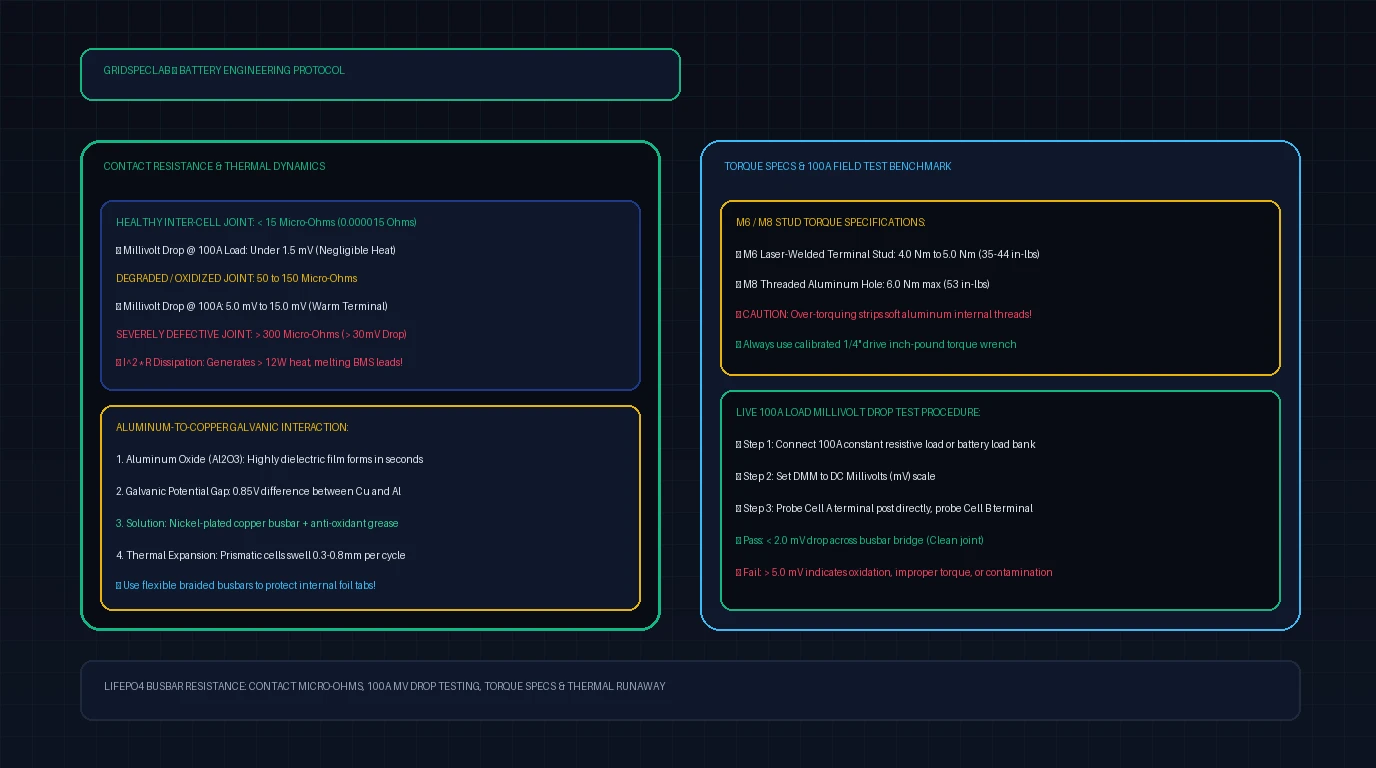
Under a 100A continuous discharge load, a healthy inter-cell busbar joint must exhibit a voltage drop of less than 2.0 millivolts (), corresponding to an interface resistance under . A connection dropping 10 mV or more is generating over 1 Watt of continuous heat directly over the cell’s delicate glass-to-metal terminal seal, leading to premature cell degradation and BMS cutoff faults.
The Physics of Contact Resistance and Joule Heating
In an electrical schematic, a copper busbar is drawn as a zero-resistance wire. In the physical realm of high-current DC battery terminals, electrical contact does not occur across the entire apparent surface area of the busbar.
Under a microscope, both the aluminum battery terminal and the copper busbar resemble jagged mountain ranges. Current transfers only through microscopic high spots called a-spots (asperities). The constriction of current streamlines through these microscopic contact points generates constriction resistance (), while surface films (oxides and contaminants) generate film resistance ():
   Busbar (Copper)       ▲ Current Streamlines Constricting
 ════════════════════════╡╞════════════════════════
    /\  /\  /\  /\  /\   ││  <-- Microscopic Asperities (A-Spots)
 ────────────────────────┼┼────────────────────────
    \/  \/  \/  \/  \/   ││  <-- Dielectric Aluminum Oxide Film
 ════════════════════════╡╞════════════════════════
   Cell Terminal Post (Aluminum)
The Destructive Math of Heating
Consider what happens when contact resistance increases from an optimal to an unoptimized (0.000250 Ohms) due to poor torque or oxidation:
At 50A Discharge (Typical Baseline Inverter Draw):
At 150A Discharge (Heavy Heat Pump or Induction Cooktop Surge):
Five watts of heat concentrated inside an M6 washer area (less than ) acts as a high-density miniature soldering iron. This heat rapidly softens the plastic insulation collars of the terminal post, melts the silicone insulation of thin BMS balance sense wires, and accelerates electrolyte breakdown inside the upper header space of the prismatic cell.
Furthermore, because BMS balance leads measure voltage at the busbar terminal ring, this artificial drop is subtracted directly from the real cell voltage reading. During discharge, the BMS believes the cell has collapsed below , triggering a premature system shutdown while the actual battery chemistry is still holding over remaining capacity!
Aluminum-to-Copper Galvanic Chemistry and Oxidation
Prismatic LiFePO4 cells (such as EVE 280K, EVE 314Ah, REPT, CATL, and Lishen) feature terminal posts made of pure electrical-grade aluminum (1000 series aluminum) on both the positive and negative terminals, or an aluminum positive terminal paired with a copper negative terminal.
Most DIY builders connect these cells using solid or flexible copper busbars. This creates two distinct chemical hazards:
Rapid Aluminum Oxide () Formation
The instant bare aluminum is exposed to atmospheric oxygen, a transparent layer of aluminum oxide () forms in less than 100 milliseconds.
Unlike copper oxide, which retains moderate electrical conductivity, aluminum oxide is a ceramic dielectric insulator with an electrical resistivity exceeding . If you bolt a busbar onto an oxidized terminal post, current is forced to tunnel through micro-fissures in the oxide layer, driving contact resistance through the roof.
Galvanic Dissimilar-Metal Corrosion
Aluminum and copper have an electrochemical potential difference of approximately 0.85 Volts on the galvanic anodic scale:
When moisture or atmospheric humidity enters the gap between bare copper and bare aluminum, an electrochemical galvanic cell is established. The aluminum terminal post acts as the sacrificial anode and corrodes, producing powdery white aluminum hydroxide flakes () that push the busbar away from the terminal, permanently breaking the electrical bond.
The Solution: Tinned/Nickel-Plated Copper and Anti-Oxidant Compounds
To permanently eliminate galvanic corrosion and surface oxidation:
- Use Electro-Tinned or Nickel-Plated Copper Busbars: Tinning creates an intermediate electrochemical barrier (), reducing the galvanic potential difference to a safe .
- Apply an Approved Synthetic Anti-Oxidant Suspension: Applying a microscopic film of Sanchem NO-OX-ID A-Special or Ideal Noalox seals the metal interface against atmospheric air and moisture. The suspension contains microscopic zinc or conductive particles that bite through surface oxides under mechanical clamping pressure, lowering contact resistance.
Precise Torque Specifications and Thread Mechanics
One of the most common causes of terminal failure in DIY battery builds is improper torque application. Battery builders either under-torque the bolts (leading to high contact resistance and arcing) or violently over-torque them (stripping the soft aluminum threads inside the cell).
 ┌─────────────────────────────────────────────────────────┐
 │ Bolt / Serrated Belleville Washer                       │
 ├─────────────────────────────────────────────────────────┤
 │ BMS Voltage Sense Ring Terminal                         │
 ├─────────────────────────────────────────────────────────┤
 │ Flexible Tinned Copper Busbar                           │
 ├─────────────────────────────────────────────────────────┤
 │ Cell Terminal Post (Laser-Welded Aluminum Base)         │
 └─────────────────────────────────────────────────────────┘
Factory Recommended Torque Ranges
| Terminal Stud Type | Material Spec | Safe Torque Range (Metric) | Safe Torque Range (Imperial) | Danger Threshold |
|---|---|---|---|---|
| M6 Laser-Welded Stud | Stainless Steel 304 | (Snaps stud or strips weld) | ||
| M6 Blind Threaded Hole | Cast Aluminum Post | (Strips aluminum threads) | ||
| M8 Laser-Welded Stud | Stainless Steel 304 | (Structural post shear) | ||
| M8 Blind Threaded Hole | Cast Aluminum Post | (Thread pull-out) |
[!CAUTION] Never Use a Standard 3/8” or 1/2” Ratchet Standard automotive socket wrenches provide immense leverage. A technician applying light hand pressure can easily exert to of torque on an M6 bolt, instantly stripping the soft internal aluminum threads of a $150 prismatic cell. Always use a calibrated 1/4-inch drive inch-pound torque wrench.
Thread Engagement Depth Rules
When using set screws or threaded studs in blind aluminum holes:
- The stud must achieve at least 1.5 times the thread diameter of mechanical engagement into the aluminum post.
- For an M6 stud, this equals a minimum of 9.0 mm of full thread engagement ().
- Thread the stud fully into the bottom of the terminal hole by hand with a drop of blue threadlocker (Loctite 242/243), leaving sufficient exposed threads for the busbar, washer, and nut. Never use the fastening nut to drive the stud down into the hole.
Flexible Braided vs Solid Copper Busbars
In early DIY battery projects, builders universally used rigid, flat, solid copper bars ( solid bar stock). Over thousands of operating hours, many of these packs experienced sheared terminal welds and severe internal resistance spikes.
Why did this occur? Thermal and mechanical prismatic expansion.
 CHARGED STATE (Cells Swell 0.5mm each):
 [Cell 1] ===> <-- Shear Force --> <=== [Cell 2]
    │                                      │
    ▼                                      ▼
 (Rigid Solid Bar: Zero Lateral Give) ──► Fractures Internal Terminal Foil
 (Flexible U-Bend Bar: Flexes Freely) ──► Zero Stress on Cell Post!
The Physics of Prismatic Swelling
As lithium ions intercalate into the graphite anode during charging, the physical volume of the electrode stack increases. A 280Ah or 314Ah prismatic cell expands by 0.3 mm to 0.8 mm in thickness between 0% and 100% State of Charge.
Across a 16-cell series string, the total cumulative expansion can exceed 8 mm to 12 mm (nearly half an inch).
- With Solid Rigid Busbars: Because the solid bar cannot stretch or compress laterally, the expanding cells push outward against the rigidly bolted terminals. This induces massive lateral shear stress on the microscopic ultrasonic welds connecting the external terminal post to the internal positive and negative electrode foil rolls inside the cell. Over time, internal tabs tear, causing catastrophic capacity loss or internal open-circuits.
- With Multi-Layer Flexible Busbars: High-grade flexible busbars are fabricated from 10 to 20 thin laminated copper foils ( to thick) formed with an upward expansion arch or U-bend. The flexible loop absorbs 1.5mm to 3.0mm of lateral cell movement effortlessly, transmitting zero mechanical stress to the delicate terminal posts.
Step-by-Step Surface Preparation Protocol
To achieve a verified contact resistance under , follow this strict five-step chemical and mechanical surface preparation workflow prior to final assembly:
┌────────────────────────────────────────────────────────┐
│ STEP 1: Degrease Terminals (99% Isopropyl Alcohol)     │
└──────────────────────────┬─────────────────────────────┘
                           ▼
┌────────────────────────────────────────────────────────┐
│ STEP 2: Non-Metallic Scuffing (Maroon Scotch-Brite)    │
└──────────────────────────┬─────────────────────────────┘
                           ▼
┌────────────────────────────────────────────────────────┐
│ STEP 3: Secondary Lint-Free Wipe Down                  │
└──────────────────────────┬─────────────────────────────┘
                           ▼
┌────────────────────────────────────────────────────────┐
│ STEP 4: Apply Micro-Thin Layer of NO-OX-ID / Noalox    │
└──────────────────────────┬─────────────────────────────┘
                           ▼
┌────────────────────────────────────────────────────────┐
│ STEP 5: Calibrated Torque to 4.5 Nm with Belleville    │
└────────────────────────────────────────────────────────┘
Detailed Execution Steps
- Chemical Degreasing: Spray a lint-free microfiber wipe with 99% pure Isopropyl Alcohol (IPA). Thoroughly clean the top surface of the cell terminal post and both contact faces of the copper busbar to remove machine oils, fingerprints, and shipping residue. Never touch cleaned surfaces with bare fingers.
- Deoxidation Scuffing: Using a Maroon Scotch-Brite pad (Very Fine aluminum oxide grade), lightly scuff the surface of the aluminum terminal post in a cross-hatch pattern for 5 to 10 seconds.
[!WARNING] Never Use Steel Wire Brushes or Coarse Sandpaper Steel wire brushes shed microscopic iron particles that become embedded in the soft aluminum, accelerating galvanic corrosion. Coarse sandpaper creates deep gouges that dramatically reduce contact surface area.
- Secondary Solvent Wipe: Wipe away the loosened oxide dust with a clean IPA cloth until the wipe comes away pristine.
- Micro-Thin Anti-Oxidant Application: Place a pinhead-sized dab of NO-OX-ID A-Special or Noalox onto the center of the terminal. Spread it with a gloved finger until the entire contact zone is covered with a micro-thin, almost transparent sheen. Wipe away any thick excess—you do not want excess grease squeezing out into the battery enclosure.
- Stackup and Fastening: Assemble the hardware stack in the exact correct order:
- Cell Terminal Post (Bottom)
- Flexible Tinned Copper Busbar
- BMS Sense Wire Ring Lug
- Stainless Steel Belleville / Disc Spring Washer (Convex side facing upward toward the nut)
- Stainless Steel Flanged Nut (Top)
- Torque Application: Using your 1/4-inch drive torque wrench, tighten the nut in a smooth, continuous motion to 4.5 Nm (40 in-lbs). Mark the nut and stud with a permanent torque-seal paint pen to provide a visual indicator of any future vibration loosening.
Field Diagnostic Testing: The 100A Millivolt Drop Test
How do you verify whether your busbar connections are truly healthy before placing the battery bank into mission-critical home backup service?
Testing resistance with a standard multimeter will tell you nothing, as multimeters cannot resolve micro-ohms. The gold standard field diagnostic test is the Live 100A Load Millivolt Drop Test.
    [ Cell 1 Terminal ] ───────── [ Busbar ] ───────── [ Cell 2 Terminal ]
            ▲                                                  ▲
            │                                                  │
            └─────── (Red Probe)            (Black Probe) ─────┘
                                      │
                                      ▼
                      [ Multimeter on DC mV Scale ]
Testing Procedure
- Apply a 100A Steady Load: Connect a calibrated DC load bank or power your inverter to draw a continuous, steady from the battery bank. Verify the exact amperage with a calibrated DC clamp meter.
- Configure Multimeter: Set a high-precision digital multimeter (Fluke 87V or equivalent) to the DC Millivolts (mV) range.
- Probe Terminal-to-Terminal: Place the red test probe directly onto the aluminum post of Cell 1 (not on the nut), and place the black test probe directly onto the aluminum post of Cell 2.
- Record the Voltage Drop: Record the millivolt reading across each of the 15 inter-cell busbars in your 16S pack.
Interpreting Millivolt Drop Test Results
| Measured Drop @ 100A Load | Calculated Resistance () | Diagnostic Interpretation | Required Corrective Action |
|---|---|---|---|
| 0.8 mV to 1.5 mV | Optimal / Factory Grade | None. Perfect electrical connection. | |
| 1.6 mV to 3.0 mV | Acceptable | Monitored annually. Normal operation. | |
| 3.1 mV to 6.0 mV | Marginal / Degraded | Re-torque nut to 4.5 Nm. Retest. | |
| 6.1 mV to 15.0 mV | Defective Joint | Disassemble, deoxidize, re-grease, re-torque. | |
| Critical Fire Hazard | Immediate shutdown. Severe arcing risk. |
Infrared Thermal Imaging Cross-Verification
Simultaneously scan the battery bank with an infrared thermal imaging camera (such as a FLIR E4/E8 or thermal smartphone attachment) while operating under full 100A load:
- In a balanced, high-efficiency battery bank, all 15 busbars will display an identical thermal signature within ±3°F (±1.5°C) of one another.
- Any busbar running more than 10°F (5.5°C) hotter than the pack average indicates elevated contact resistance that requires immediate mechanical refurbishment.
Frequently Asked Questions
Can I use stainless steel bolts to conduct electrical current?
Stainless steel is a terrible electrical conductor. The electrical conductivity of 304 stainless steel is only about 2.5% IACS (International Annealed Copper Standard), compared to 100% for copper and 61% for aluminum. In a properly designed battery terminal, current must flow directly from the bottom face of the copper busbar into the top surface of the aluminum terminal post. The stainless steel stud and nut serve purely as a mechanical clamp to apply downward compression; they are not intended to carry electrical current.
Should the BMS sense ring terminal go under or over the busbar?
The BMS balance ring terminal should always go on top of the busbar, never between the busbar and the cell terminal post! Placing a brass, copper, or steel ring terminal underneath the busbar cuts the main contact surface area in half, drastically increasing contact resistance and causing heavy heating under high discharge currents.
Do Belleville conical spring washers make a real difference?
Yes, they are mandatory for high-performance battery banks. Prismatic battery terminals undergo thousands of thermal cycles as they heat up under discharge and cool during standby. Because aluminum, copper, and stainless steel all have different thermal expansion coefficients, flat rigid washers loosen over time. A Belleville conical disc spring washer maintains continuous spring-loaded downward clamping force (typically 800 to 1,200 lbs of mechanical pre-load) even as metals expand and contract, permanently preventing loose terminal connections.
Conclusion
Maximizing the performance, safety, and lifespan of a high-capacity LiFePO4 battery system requires treating every busbar connection as a precision electrical junction. By eliminating aluminum oxidation with Scotch-Brite and anti-oxidant grease, selecting flexible laminated busbars that accommodate prismatic cell swelling, applying strict torque limits with an inch-pound torque wrench, and validating each connection with a 100A millivolt drop test, you guarantee zero thermal hotspots, zero false BMS trips, and years of trouble-free off-grid energy storage.