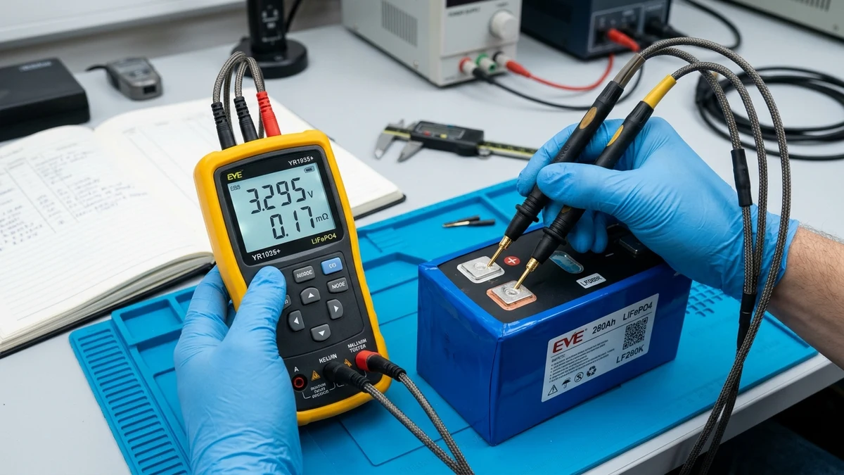
When unboxing a fresh pallet of raw lithium iron phosphate (LiFePO4) prismatic cells from an overseas supplier, checking open-circuit voltage (OCV) with a standard digital multimeter gives you almost zero insight into cell health. Because LiFePO4 exhibits an ultra-flat voltage curve between 10% and 90% state-of-charge, a degraded, heavily cycled second-life cell and a brand-new factory Grade A cell can sit side-by-side on your workbench reading identical resting voltages of .
To separate genuine prime cells from rejected factory b-grades, recycled EV packs, and internally damaged units, battery engineers rely on Internal Resistance (IR) testing.
Specifically, the four-wire 1kHz AC Internal Resistance test is the international IEC 61960 standard for electrochemical cell impedance. In this engineering benchmark guide, the GridSpecLab hardware team demonstrates how to use the ubiquitous YR1035+ Milliohm Meter to audit raw cells, avoid common measurement errors, identify counterfeit capacity ratings, and sort sixteen cells into a harmonized, perfectly matched 48V battery bank.
Voltage tells you a battery’s resting charge; internal resistance tells you its true internal health. Brand new Grade A EVE 280Ah and 304Ah prismatic cells should measure between 0.15 mΩ and 0.20 mΩ at room temperature. Testing every cell with a 4-wire Kelvin meter like the YR1035+ prior to busbar assembly takes under 10 minutes and prevents building high-resistance runner cells into your 48V homestead battery bank.
Check YR1035+ on Amazon →
Why Internal Resistance Is the Definitive Test for Cell Health
Internal resistance represents the total opposition a battery offers to the flow of alternating or direct electrical current. In a prismatic LiFePO4 cell, this resistance is composed of two primary physical mechanisms:
- Ohmic Resistance (): The bulk electronic resistance of the aluminum positive current collectors, copper negative foils, terminal weld joints, and electrolyte ionic conductivity.
- Polarization Resistance (): The electrochemical kinetic resistance at the electrode-electrolyte interface (SEI layer) and solid-state lithium ion diffusion resistance inside active graphite and iron phosphate crystal lattices.
When high discharge currents pass through internal resistance, two destructive phenomena occur governed by Ohm’s Law and Joule Heating:
If one cell in a 16S battery pack has an internal resistance of while the other fifteen cells measure , drawing 150 Amperes through the pack causes that single outlier cell to suffer double the voltage sag ( vs ) and generate double the thermal heat.
Under continuous inverter load, this cell hits low-voltage cutoff prematurely, triggering the BMS to shut down the entire system while the remaining cells still have 30% capacity remaining.
Operating Principles of Four-Wire Kelvin Probe Measurement
Standard digital multimeters measure resistance using a two-wire configuration: current is pumped down the test leads, and voltage drop is measured across the same conductors. While adequate for measuring kilo-ohms or ohms, two-wire probes are utterly useless for battery cells:
- Standard multimeter copper test leads possess between and of wire resistance ().
- Surface contact resistance between probe tips and battery terminals introduces another of variable noise.
- Trying to measure a LiFePO4 cell with a standard meter results in measuring the probe leads rather than the cell chemistry.
Two-Wire Lead Resistance Error
Injects current and samples voltage through identical leads. Probe wire resistance, alligator clip contact impedance, and terminal oxidation are included in the reading, distorting small milliohm measurements by up to 2,000%.
- Cannot distinguish 0.17 mΩ from 50.0 mΩ
- Highly sensitive to probe tip hand pressure
- Fails to inject AC excitation signal
Four-Wire Kelvin Isolation
Separates the current excitation loop () from the voltage sense loop (). Because virtually zero current flows through the high-impedance sense pins, lead resistance drops to zero in the measurement equation.
- 1kHz AC excitation eliminates DC offset
- Precision down to 0.01 milliohms (10 micro-ohms)
- Spring-loaded concentric dual pins guarantee solid bite
The YR1035+ utilizes a calibrated 1kHz AC sinusoidal current injection. Operating at 1,000 Hertz bypasses slow electrochemical capacitive double-layer effects, isolating pure ohmic internal resistance without charging or discharging the cell during measurement.
Baseline Internal Resistance Benchmarks: Grade A vs Degraded Cells
When evaluating large-format prismatic LiFePO4 cells, use the manufacturer factory specification sheets as your golden benchmark. High-quality cells from manufacturers like EVE Energy, CATL, REPT, and Gotion exhibit exceptionally tight resistance distributions.
| Cell Model & Chemistry | Nominal Capacity | Factory Grade A Specification | GridSpecLab Acceptable Benchmark | Degraded / Second-Life Reject |
|---|---|---|---|---|
| EVE LF280K v3 (Grade A) | 280 Ah | |||
| EVE MB30 / MB31 (Grade A) | 304 Ah / 314 Ah | |||
| CATL 3.2V 280Ah (LFP) | 280 Ah | |||
| REPT 280Ah Prismatic | 280 Ah | |||
| Generic / Re-wrapped Grade B | Rated 280 Ah | Not Specified | (Severe Sag) | |
| Degraded EV Salvage Cell | Used ~200 Ah | Degraded | Unusable for 1C High Surge |
Notice that genuine Grade A cells from prime manufacturing lots routinely beat their conservative datasheet maximum ratings: while EVE specifies , brand new cells straight from factory wooden pallets typically test between and .
Step-by-Step Testing and Data Logging Protocol
To achieve repeatable, laboratory-grade measurements with the YR1035+, follow this four-phase testing protocol:
Probe Preparation and Zero Calibration
Power on the YR1035+ meter. By default, the unit operates in Auto-Range mode.
- Inspect the spring-loaded Kelvin probe pins. Each probe tip contains two distinct electrical contacts: an outer collar (current path) and a center needle (sense path). Ensure the center needles slide freely on their internal springs.
- Short the two probe tips firmly together. The meter should display .
- If a residual offset of or appears due to lead twist or temperature shift, press and hold the HOLD / ZERO key for three seconds to zero out the baseline.
Terminal Contact Mechanics and Oxide Penetration
Aluminum and copper battery terminal studs develop thin microscopic oxide layers when exposed to atmospheric humidity. Aluminum oxide () is a potent electrical insulator.
- Lightly wipe each terminal surface with an isopropyl alcohol pad to remove shipping grease or residue.
- Do not gouge or sand the laser-welded aluminum terminal pad with coarse abrasives.
- Hold the Kelvin probes perpendicular (90 degrees) to the terminal face.
- Press down with moderate, steady hand pressure (approx. 2 to 3 lbs of downward force). You will feel the inner needle spring compress. This mechanical pressure bites through surface oxidation, providing intimate metallic contact.
Temperature Compensation and Ambient Normalization
Electrochemical internal resistance is inversely proportional to temperature: cold electrolyte exhibits higher viscosity and sluggish ion mobility, causing internal resistance to rise significantly.
- Always allow newly delivered cells to acclimate in your conditioned workspace for at least 12 to 24 hours prior to benchmarking.
- Conducting tests on a freezing cell in an unheated garage at can yield artificially inflated readings of on a cell that tests at at room temperature ().
- Test all sixteen cells during the same testing session so ambient conditions remain identical.
Recording Open-Circuit Voltage and Milliohms
The YR1035+ displays both parameters simultaneously on its backlit screen:
- Top line: Open-circuit voltage (e.g.,
3.294V). - Bottom line: AC internal resistance (e.g.,
0.172 mΩ). - Press the HOLD button to freeze the display, write the values directly onto the blue cell shrink wrap using a silver metallic permanent marker, and log the numbers into a digital spreadsheet.
Cell Grouping and Matching Strategies for Series Battery Packs
Once all sixteen cells have been benchmarked, do not assemble them randomly into your server rack chassis. Sorting and grouping cells strategically prevents early capacity exhaustion and minimizes active balancer workload.
Identifying Outliers and Rejects
Examine your sixteen-cell dataset for standard deviation:
- In a prime lot of Grade A cells, all sixteen units will fall within a tight window of (for example, between and ).
- If fifteen cells measure to , but cell twelve measures , flag cell twelve immediately.
- Contact your vendor for a warranty replacement before torquing busbars or installing compression plates. Once assembled into a battery box, vendors routinely refuse warranty claims.
Strategic Physical Placement in Server Rack Enclosures
In standard 19-inch battery enclosures (such as the Seplos Mason or Pace BMS boxes), the cells situated in the physical center of the enclosure experience slightly higher operating temperatures ( warmer) than the exterior cells adjacent to steel side walls.
- Place cells with slightly lower internal resistance (e.g., ) in the central slots, as they generate slightly less internal resistive heat during heavy discharge.
- Position cells with marginally higher resistance (e.g., ) along the exterior perimeter where ambient convective cooling is superior.
Common Testing Pitfalls and False High Resistance Readings
If your YR1035+ reports unexpectedly high resistance readings on brand new cells, verify these common laboratory errors before assuming your cells are defective:
- Angled Probe Placement: Tilting the probe handle at an angle prevents one of the two concentric Kelvin pins from contacting the terminal face, breaking the four-wire sense circuit and causing the meter to flash or display OL (Over Limit).
- Testing Across Busbars: Always measure directly on the raw battery cell terminal pad or stud base. Measuring on top of a nickel-plated copper busbar or terminal bolt washer adds busbar bulk resistance and contact transition resistance to your reading.
- Depleted Meter Battery: The YR1035+ is powered by an internal 3.7V lithium-ion pouch cell. When the battery icon drops to one bar, the internal 1kHz sinusoidal excitation oscillator can lose amplitude stability, introducing erratic measurement drift. Recharge the meter fully via USB before testing.
- Cable Strain and Broken Sense Leads: The flexible silicone leads connecting the Kelvin probes to the four-pin aviation connector endure repeated flexing. If a sense wire breaks internally, the meter will display erratic fluctuations. Inspect lead continuity periodically.
Frequently Asked Questions About LiFePO4 Resistance Testing
What is the difference between AC internal resistance and DC internal resistance?
AC internal resistance (measured at 1kHz by the YR1035+) captures pure ohmic resistance (electronic conductors and electrolyte mobility) without polarization effects. DC internal resistance (DCIR) is measured by applying a heavy continuous discharge load (e.g., 50A for 10 seconds) and dividing the instantaneous voltage drop by discharge amperage (). DCIR is always slightly higher than AC IR because it incorporates electrochemical double-layer polarization. AC IR is faster, non-destructive, and the universally accepted industry standard for incoming cell quality inspection.
Can I test cells while they are connected in series with busbars?
No. While testing connected cells will not damage the YR1035+ (the meter input is rated up to 100V DC), the 1kHz AC excitation signal will propagate through parallel current paths across neighboring cells and inverter input capacitors, corrupting individual cell accuracy. Always disconnect busbars and test each cell in complete electrical isolation.
Does cell state-of-charge (SoC) affect internal resistance?
Between 20% and 80% state-of-charge, LiFePO4 internal resistance is remarkably flat and constant. However, internal resistance spikes noticeably below 10% SoC (due to lithium starvation at the cathode) and rises slightly above 95% SoC. For consistent benchmarking, test your cells at their typical factory shipping storage charge (approx. 30% to 50% SoC, or ).
Can a BMS measure internal resistance accurately?
Most smart BMS units (such as JK, Seplos, or Daly) only estimate DC internal resistance dynamically under heavy continuous load using rough voltage-drop math. They lack four-wire Kelvin hardware and 1kHz AC oscillators, making their reported milliohm numbers coarse approximations. The YR1035+ remains the definitive gold standard for pre-assembly screening.