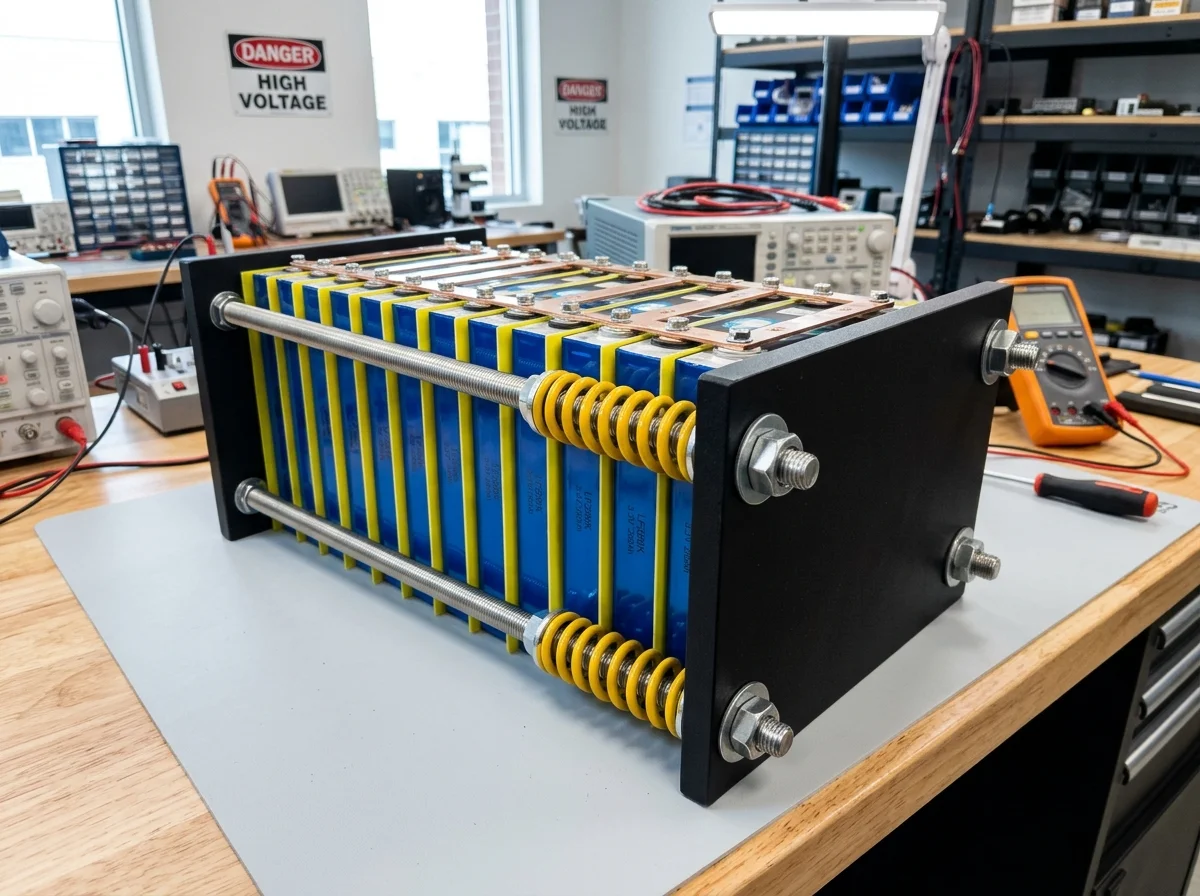
When building a custom 48V or 24V energy storage system using large-format prismatic lithium iron phosphate cells—such as EVE 280Ah, 304Ah, or 314Ah units—mechanical compression is frequently misunderstood. Online forums are flooded with conflicting advice, ranging from clamping cells rigidly with wooden 2x4s to leaving cells completely uncompressed in loose battery boxes.
Both extremes are catastrophic for cell health. Rigid unyielding clamping causes extreme mechanical stress during full charge, while zero compression allows graphite layers to delaminate over cycling, cutting battery lifespan by more than 60%.
To achieve the manufacturer-rated 6,000 to 8,000 cycle lifespan, manufacturers like EVE Energy, CATL, and REPT mandate a continuous mechanical compression force of 300 kgf (approx. 10–12 psi / 2,942 Newtons) applied across the broad face of the cells.
In this engineering guide, we break down the solid-state physics of lithium intercalation, calculate spring compression distances using Hooke’s Law, compare structural endplate materials, and provide step-by-step instructions for building a professional-grade battery compression fixture.
Compression does not mean squeezing cells as tight as possible. A proper compression fixture uses calibrated die springs that maintain a steady 300 kgf force while allowing cells to expand microscopically as State of Charge (SoC) climbs from 0% to 100%. Without springs, thermal and chemical expansion will bend endplates, crack welds, or crush internal separator membranes.
The Physics of Lithium Intercalation and Cell Swelling
To understand why compression is mandatory, we must examine the nanometer-scale electrochemistry occurring inside every LiFePO4 cell.
During battery charging, lithium ions () leave the iron phosphate cathode, migrate across the liquid electrolyte through a microscopic separator, and insert themselves into the layered crystalline structure of the graphite anode. This process is called intercalation.
0% to 100% State of Charge
As graphite absorbs lithium ions, the anode expands physically by approximately 1.0% to 1.5% in thickness. For an EVE 280Ah cell with a nominal 71.7mm thickness, this creates 0.7mm to 1.1mm of linear expansion per cell (over 16mm of total pack breathing on a 16S bank).
Springs absorb this daily cyclic expansion smoothly.Uncompressed Battery Failure
Without external mechanical pressure, repetitive cycling causes microscopic gaps to form between the active material and the copper/aluminum current collectors. The solid electrolyte interphase (SEI) thickens unevenly, internal resistance spikes, and the cell permanently balloons.
Cuts cycle life from 8,000 cycles to under 2,500.Pressure Mathematics: Translating 300 kgf to PSI and Hooke’s Law
Manufacturers specify compression force in kilogram-force (kgf) or Newtons. To build a fixture with threaded rods and springs, we must translate force into surface pressure (PSI) and spring compression distance.
Calculating Surface Pressure (PSI)
Let us calculate the exact surface pressure for standard 71173 prismatic cells (such as the EVE LF280K, LF304, or LF314):
- Cell Face Width:
- Cell Face Height:
- Surface Area ():
- Target Force ():
Therefore, the target surface pressure is 12.0 PSI (+/- 1.5 PSI) across the face of the cells.
Calculating Spring Deflection via Hooke’s Law
To achieve 300 kgf without an expensive hydraulic load cell, we place die springs over four threaded rods. By using Hooke’s Law, we can calculate the exact distance (in millimeters or inches) each spring must be compressed.
Hooke’s Law states:
Where:
- = Force applied per spring
- = Spring rate (stiffness constant, provided by spring manufacturer in N/mm or lbs/in)
- = Compression deflection distance
When using four identical springs (one on each corner rod of the endplate):
Practical Calculation: ISO Standard Blue Die Springs
Suppose you select four standard ISO 10243 Blue Light-Load Die Springs (Outer Diameter 25mm, Inner Hole 12.5mm, Free Length 50mm) with a certified spring constant of .
How to Execute: Measure the uncompressed free length of your spring with digital calipers (e.g. 50.0mm). Tighten your corner nuts evenly until the spring length measures exactly . You have now applied exactly 300 kgf of force with mathematical precision.
Bill of Materials: Endplates, Rods, and Insulation
A battery compression fixture must remain rigid under 660 lbs of continuous stress for 15 to 20 years. Selecting weak materials will cause the fixture to bend in the middle, starving center cells of pressure.
| Component | Minimum Specification | Recommended Material | Why It Matters |
|---|---|---|---|
| Endplates | 3/8” (9.5mm) Aluminum or 1/2” (12.7mm) Steel | 6061-T6 Aluminum or Grade A36 Steel | Thin 1/8” aluminum or 3/4” plywood will bow outward in the center under 660 lbs. |
| Threaded Rods | 3/8” (10mm) diameter | Grade B7 Alloy Steel or 304 Stainless | Standard zinc hardware store all-thread can strip or stretch over time. |
| Die Springs | 4x ISO 10243 Standard Springs | Blue (Light Load) or Red (Medium Load) | Provides linear, predictable spring rates that absorb cyclic thermal expansion. |
| Inter-Cell Insulators | 0.5mm – 1.0mm thickness | FR4 Fiberglass / Epoxy Sheets | Prevents dead shorts if thin blue PET cell shrink wrap wears through. |
| Hardware | Flanged Nyloc locking nuts + thick washers | Grade 8 or Stainless Steel | Distributes spring load evenly without gouging aluminum endplates. |
Step-by-Step DIY Assembly Protocol
Building a professional 16S 48V compression fixture requires methodical craftsmanship to prevent cell casing damage or accidental busbar short circuits.
Cell Stacking & FR4
Place pre-cut FR4 fiberglass insulation sheets between every single cell and between end cells and aluminum endplates. Align terminals strictly using an aluminum straightedge.
Rods & Spring Mounting
Slide 4 threaded rods through corner holes in the endplates. Install hardened washers, followed by die springs, flat washers, and hex nuts on each corner.
Cross-Torque Tightening
Tighten corner nuts in an alternating criss-cross pattern (Top-Left, Bottom-Right, Top-Right, Bottom-Left) in 2mm increments. Verify spring deflection with calipers until target is reached.
Busbars & BMS Wiring
Install flexible laminated copper busbars only after final compression is locked. Wire your JK Active BMS balance harness and verify voltages.
Critical Failure Modes: Uncompressed vs. Over-Compressed
Understanding the consequences of incorrect compression helps avoid dangerous mistakes during commissioning.
Zero Compression (Loose Pack)
- What Happens: Cells swell freely during charge. Active cathode/anode particles lose physical contact with the copper substrate.
- Result: Internal resistance doubles within 300 cycles. Capacity fades rapidly to 70% within 3 years. The pack develops extreme cell voltage divergence (runner cells) during charging above 3.45V.
Rigid Over-Compression (No Springs)
- What Happens: Cells are clamped rock-solid with bolts and unyielding steel plates.
- Result: When the battery reaches 100% SoC or warms up to 105°F during summer inverter operation, thermal expansion creates crushing forces exceeding 1,200 kgf. This crushes internal polyethylene separators, causing localized micro-shorts, high self-discharge, and potential thermal events.
Center-Bowing Endplates
- What Happens: The builder uses thin 1/8” aluminum or wood plates. The corners are clamped tight, but the center of the plate bows outward like a bowstring.
- Result: The outer edges of the cells experience 25 PSI of localized shear stress, while the middle of the cell face receives 0 PSI.
Commercial Compression Fixtures vs. DIY Fabrication
If you lack access to a drill press, metal saw, and metal sourcing, commercial pre-engineered fixtures offer a turnkey alternative:
- DIY Custom Fabrication (Cost: $75–$110): Sourcing raw 6061-T6 aluminum plates from online metal distributors, McMaster-Carr Grade B7 threaded rod, and ISO die springs is the cheapest route for skilled DIYers.
- Turnkey Server Rack Enclosures (Cost: $350–$550): Commercial DIY battery boxes (such as Seplos Mason, Sunfunkit, or Amy Wan DIY kits) include built-in spring-loaded compression mechanisms, integrated 200A circuit breakers, busbars, and pre-wired BMS harnesses. They provide professional aesthetics and code-compliant enclosures for home backup.
Conclusion and Final Checklist
Compressing your LiFePO4 cells to 300 kgf (12 PSI) using calibrated die springs is not an optional aesthetic choice—it is a foundational engineering requirement to guarantee an 8,000-cycle (20+ year) battery lifespan.
Final Build Checklist:
- FR4 insulation placed between every cell and against metal endplates.
- Endplates measure at least 3/8-inch (10mm) thick aluminum to prevent center deflection.
- Four calibrated die springs installed to absorb cyclic charging expansion.
- Spring deflection measured with digital calipers to verify exact Hooke’s Law compression.
- Flexible busbars installed after compression to prevent shearing terminal studs.
- Active BMS and low-temperature cutoff installed to protect against sub-freezing charging.
For optimal balancing performance across large compressed prismatic banks, pair your system with a dedicated JK BMS Active Balancer and review our 48V Solar Battery Sizing Guide to properly match your inverter capacity.