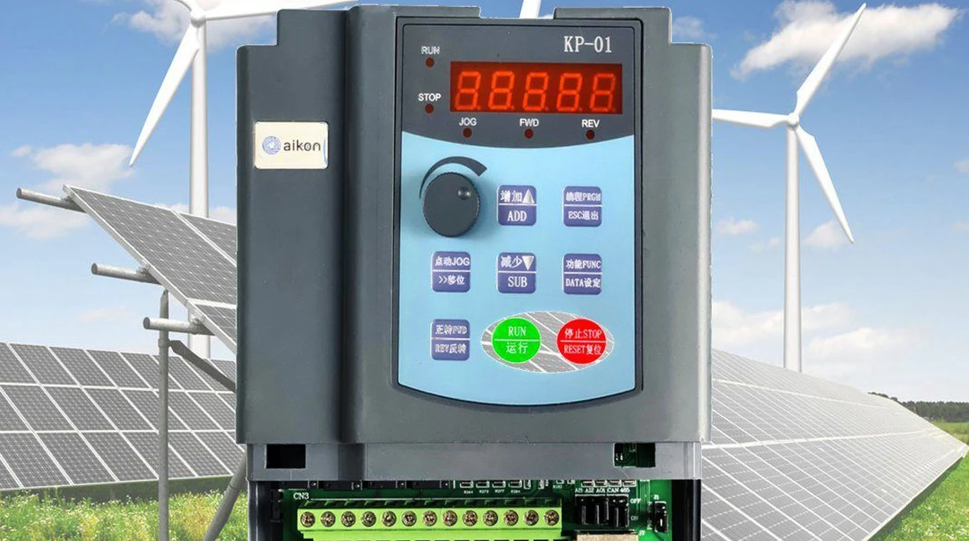
In agricultural irrigation, livestock ranching, and remote homesteading, water is energy. Traditionally, off-grid property owners attempted to power deep well submersible pumps by building massive battery banks: combining dozens of lead-acid or lithium cells, large solar charge controllers, and heavy split-phase inverters.
However, well pumps are brutal electrical loads. Starting a conventional single-phase induction motor demands between four and seven times its running amperage in Locked Rotor Amps (LRA). This massive inrush current rapidly degrades chemical batteries, trips solid-state inverters on hardware faults, and drives system costs into the tens of thousands of dollars.
Direct solar pumping eliminates the battery bank entirely. By coupling a high-voltage photovoltaic array to a purpose-built Solar Variable Frequency Drive (VFD)—such as units manufactured by Veichi or INVT—homesteaders can drive standard, ultra-reliable three-phase submersible AC motors directly from the sun. Rather than storing chemical energy in lithium cells to pump water at night, the system pumps surplus water into elevated cisterns, poly tanks, or ponds during daylight hours. Gravity provides pressurized water around the clock with zero electronic wear.
This electrical engineering guide covers the electromagnetic physics of solar VFD direct drives, explains DC bus voltage sizing calculations, details critical motor protection thresholds, and provides step-by-step field wiring and commissioning protocols.
A solar VFD converts DC solar electricity into pulse-width modulated (PWM) three-phase AC without requiring a battery. Because three-phase motors generate rotating stator magnetic fields without starting capacitors, centrifugal switches, or starting windings, they deliver superior electrical efficiency, generate zero starting current spikes, and run for decades with unmatched mechanical reliability.
Why Batteries Fail in Water Pumping and How Solar VFDs Operate
Chemical storage batteries represent the single most fragile link in any off-grid water pumping system:
- Temperature Vulnerabilities: Battery sheds experience severe seasonal temperature extremes. Freezing winter conditions halt lithium charging, while scorching summer heat accelerates electrolyte dry-out in lead-acid banks.
- Inverter Standby Drain: Maintaining 40/60 PSI water pressure with a conventional inverter requires keeping the inverter powered twenty-four hours a day, dissipating between 25 and 60 Watts of continuous idle tare loss just waiting for a faucet to open.
- Cyclic Wear and Replacement Costs: High-amperage surge cycles degrade battery health, necessitating expensive multi-thousand-dollar replacements every five to ten years.
┌────────────────────────────────────────────────────────────────────────┐
│               DIRECT SOLAR VFD DRIVE SYSTEM TOPOLOGY                   │
└────────────────────────────────────────────────────────────────────────┘

 [ High-Voltage Solar Array (300V-400V DC) ]
                     │
                     ▼
       ┌───────────────────────────┐
       │   2-Pole DC Disconnect    │ (1,000V DC Rated)
       └─────────────┬─────────────┘
                     │
                     ▼
       ┌───────────────────────────┐
       │     SOLAR PUMP VFD        │ ◄─── Tank High-Water Float Switch
       │ (MPPT DC-to-AC Inverter)  │ ◄─── Well Borehole Low-Water Sensor
       └─────────────┬─────────────┘
                     │
                     ▼
       ┌───────────────────────────┐
       │  AC Output Line Reactor   │ (For Well Drops > 150 Feet)
       └─────────────┬─────────────┘
                     │
                     ▼
 [ Standard 3-Phase 230V Submersible Motor (Franklin / Grundfos) ]
The Internal Operation of a Solar VFD
A modern solar VFD consists of three primary engineering stages:
- Dynamic MPPT Controller: Unlike standard industrial VFDs that assume an infinite, stiff utility grid on their input terminals, a solar VFD constantly measures incoming DC array voltage. If a cloud passes overhead and array current drops, standard drives would trip on undervoltage. The solar VFD instantly responds by throttling its output AC frequency (and corresponding motor RPM) downward, keeping array voltage pinned at its maximum power point ().
- High-Voltage DC Bus: incoming photovoltaic energy charges a bank of industrial electrolytic capacitors, smoothing high-frequency ripple.
- Six-Switch IGBT Inverter Bridge: Insulated Gate Bipolar Transistors (IGBTs) chop the high-voltage DC bus into variable-frequency, variable-voltage three-phase AC waveforms via sinusoidal pulse-width modulation (SPWM).
Array Voltage Sizing Calculations and DC Bus Mathematics
The most critical engineering requirement in solar VFD sizing is ensuring the photovoltaic string voltage perfectly matches the internal DC bus requirements of the three-phase AC motor.
The Peak Voltage Synthesis Formula
In any three-phase PWM inverter, synthesizing a clean root-mean-square (RMS) AC line-to-line voltage requires that the peak-to-peak DC bus voltage exceed the peak of the sinusoidal AC output wave:
For a standard 230V three-phase submersible motor:
To account for switching dead-time, IGBT forward conduction voltage drops, and internal filter impedance losses, the photovoltaic array must deliver a real-world operating voltage () of at least 330V to 360V DC under full midday solar heat.
┌────────────────────────────────────────────────────────────────────────┐
│           PV ARRAY VOLTAGE MATCHING WINDOW (230V 3-PHASE PUMP)         │
├────────────────────────────────────────────────────────────────────────┤
│ Absolute Minimum VFD Run Voltage: 220V DC                              │
│ Full-Speed (60Hz / 230V AC) Operating Voltage: 330V to 380V DC Vmp     │
│ Optimal Midday String Target: 350V to 360V DC @ 115°F Panel Cell Temp  │
│ Maximum Safe Open-Circuit Voltage (Voc): 420V DC @ 0°F Winter Ambient  │
│ Absolute VFD Hardware Overvoltage Trip: 450V DC                        │
└────────────────────────────────────────────────────────────────────────┘
Step-by-Step String Sizing Example
Suppose we are powering a 2-Horsepower, 230V three-phase submersible pump (drawing 1,500 Watts running power) using standard 400W commercial solar panels with the following manufacturer ratings:
- Rated Maximum Power Voltage (): 37.2 Volts (at standard test conditions)
- Open Circuit Voltage (): 45.0 Volts
- Temperature Coefficient of :
-
Calculate Number of Panels for Operating Vmp: To achieve 360V DC operating voltage under hot summer conditions ( cell temperature, which reduces voltage by roughly 10%):
-
Verify Maximum Cold-Weather Voc Safety: On a freezing winter morning at , panel open-circuit voltage rises: Engineering Warning: If your VFD carries a 450V maximum input limit, a 10-panel string will trigger an overvoltage trip in deep winter. You must select an eight- or nine-panel string with higher individual cell voltage or choose a higher-voltage 800V VFD platform.
The Critical Role of Minimum Frequency Thresholds
Standard surface centrifugal pumps can throttle down to very low speeds without mechanical damage. Submersible deep well pumps, however, operate under a completely different set of physical laws.
┌────────────────────────────────────────────────────────────────────────┐
│            SUBMERSIBLE THRUST BEARING LUBRICATION COLLAPSE             │
├────────────────────────────────────────────────────────────────────────┤
│ Above 35 Hertz (1,800+ RPM):                                           │
│  • High centrifugal shaft velocity draws fluid between bearing shoes   │
│  • Hydrodynamic water film completely separates carbon and steel faces │
│  • Mechanical friction approaches zero (Decades of operational life)   │
├────────────────────────────────────────────────────────────────────────┤
│ Below 30 Hertz (Under 1,500 RPM):                                      │
│  • Rotational velocity drops below critical hydrodynamic threshold     │
│  • Water film collapses; Kingsbury bearing shoes enter boundary contact│
│  • Carbon wear accelerates 50x; motor burns out within weeks           │
└────────────────────────────────────────────────────────────────────────┘
The Kingsbury Hydrodynamic Bearing Law
Submersible well motors (including all industry-standard Franklin Electric, Pentair, and Grundfos water-lubricated stators) do not utilize sealed ball bearings. They rely on Kingsbury-type hydrodynamic thrust bearings lubricated entirely by ambient well water.
At normal operating speeds (50Hz to 60Hz), rotational velocity forces a microscopic, pressurized wedge of water between the tilting bearing pads and the rotating stainless thrust runner. The rotor literally floats on water with zero metal-to-metal contact.
When cloud cover drops solar array output and the VFD throttles pump speed below 30 to 35 Hertz, centrifugal velocity becomes insufficient to sustain this pressurized water wedge. The bearing faces touch, generating extreme frictional heat that rapidly wears away the carbon thrust pads.
Mandatory VFD Parameter Setting:
Every solar pump installer must program the drive’s Lower Frequency Limit (Parameter F0.08 on Veichi drives, or P0.12 on INVT drives) to no lower than 35.0 Hertz. When solar irradiance drops so low that the array cannot sustain 35Hz, the drive must initiate a graceful shutdown rather than allowing the pump to churn at low RPM.
Leading Hardware Comparison: Veichi SI23 vs INVT BPD Series
Two industrial automation manufacturers dominate the decentralized solar pumping market across the globe: Veichi Electric and INVT Automation.
| Engineering Feature | Veichi SI23 Series Solar Pump Inverter | INVT BPD Series Solar VFD Drive |
|---|---|---|
| Chassis Protection Rating | IP65 Outdoor Sealed Die-Cast Aluminum | IP20 Indoor (IP65 Outdoor Box Optional) |
| Cooling Architecture | Natural Passive Convection (No external fans) | Internal Forced-Air Cooling Fan |
| Peak MPPT Tracking Efficiency | 99.0% Dynamic Accuracy | 99.0% Dynamic Accuracy |
| Input DC Voltage Range | 250V to 450V DC (230V Model) | 250V to 450V DC (230V Model) |
| Automatic Sleep and Wakeup | Sunlight-based auto sleep and wake functions | Multi-stage irradiance sleep tracking |
| Hybrid AC/DC Switching | External manual transfer switch required | Integrated automatic AC/DC auto-switch module |
| Sensor Interlock Inputs | Dual terminals for well probe and tank float | Dual terminals for digital float and pressure switch |
| Motor Compatibility | 3-Phase AC Asynchronous & Permanent Magnet | 3-Phase AC Asynchronous & PMSM |
| Field Reliability Rating | 9.7 / 10 (Best for Remote Desert/Ranch Rigs) | 9.4 / 10 (Best for Shed-Mounted Systems) |
Veichi SI23 Strengths
The Veichi SI23 stands out for remote off-grid harsh environments. Its entire enclosure is an IP65-sealed, finned die-cast aluminum heatsink. It features no open ventilation slits, preventing desert dust, wasps, and moisture from penetrating the circuit board. It operates completely fanless, eliminating the leading mechanical failure point of remote electronic hardware.
INVT BPD Strengths
The INVT BPD series excels in hybrid systems where a portable generator or utility grid line serves as an occasional backup. It offers seamless automated bypass switching: if a multi-day overcast storm depletes water tanks, the drive can automatically signal a dry contact to crank a backup diesel generator, running the three-phase pump until sunlight returns.
Field Wiring Schematics and Cable Distance Filters
Deep well installations require long submersible drop cables that introduce severe electrical transmission line phenomena:
┌────────────────────────────────────────────────────────────────────────┐
│            OFF-GRID SOLAR VFD FIELD WIRING SCHEMATIC                   │
└────────────────────────────────────────────────────────────────────────┘

 [ High-Voltage Solar Array ]
     │ (+)          │ (-)
     ▼              ▼
 ┌──────────────────────┐
 │  2-Pole DC Breaker   │ (500V / 20A DC-Rated Disconnect)
 └──────────┬───────────┘
            │
            ▼
 ┌──────────────────────────────────────┐
 │       SOLAR VFD CONTROLLER           │
 │                                      │
 │  Terminals: [ PV+ ]      [ PV- ]     │
 │                                      │
 │  Interlocks:                         │
 │   • Terminals DI1 / COM ─────────────┼──► Elevated Tank High-Level Float
 │   • Terminals DI2 / COM ─────────────┼──► Borehole Well Low-Water Probe
 │                                      │
 │  Outputs:   [ U ]   [ V ]   [ W ]    │
 └───────────────┬───────┬───────┬──────┘
                 │       │       │
                 ▼       ▼       ▼
 ┌──────────────────────────────────────┐
 │       AC OUTPUT LINE REACTOR         │ (Mandatory for Cable Runs > 150 Feet)
 └───────────────┬───────┬───────┬──────┘
                 │       │       │
                 ▼       ▼       ▼
 [ Heavy-Duty 3-Conductor Submersible Drop Cable (10 AWG to 6 AWG) ]
                 │
                 ▼
 [ 3-Phase 230V AC Submersible Motor at Well Bottom ]
The Reflected Wave Phenomenon (dV/dt Protection)
The output of an IGBT-based VFD is not a smooth sine wave; it is a train of extremely steep square-wave pulses with rise times under one hundred nanoseconds.
When these high-speed pulses travel down two hundred to six hundred feet of submerged well wire, the motor terminals present an impedance mismatch relative to the cable. The voltage wave reflects back on itself, creating voltage spikes reaching two to three times the nominal DC bus voltage (over 1,000 Volts).
These continuous voltage spikes will puncture the thin enamel insulation of standard motor windings, causing premature stator shorts.
- Cable runs under 150 feet: Standard twisted submersible cable is acceptable.
- Cable runs between 150 and 500 feet: You must install an AC Output Line Reactor (typically a 3% to 5% impedance inductor) directly between the VFD output terminals and the drop cable.
- Cable runs exceeding 500 feet: Install a specialized dV/dt filter or sine-wave filter to smooth pulse edges and preserve motor longevity.
Field Commissioning and Verification Checklist
Follow this systematic step-by-step checklist prior to energizing your solar pumping system:
┌────────────────────────────────────────────────────────────────────────┐
│               SOLAR VFD COMMISSIONING CHECKLIST                        │
├────────────────────────────────────────────────────────────────────────┤
│ [ ] Measure open-circuit voltage (Voc) at DC disconnect before closing │
│ [ ] Verify Voc is under 420V DC and polarity is strictly correct       │
│ [ ] Check motor lead megohmmeter insulation resistance (> 100 M-Ohm)   │
│ [ ] Program motor nameplate parameters: Rated Volts, Amps, RPM, and kW │
│ [ ] Set parameter Minimum Operating Frequency to 35.0 Hertz            │
│ [ ] Set Acceleration Ramp Time to 2.0 to 3.0 seconds (Fast soft-start) │
│ [ ] Test tank float switch: Ensure drive halts immediately on full tank│
│ [ ] Observe rotation direction: If flow is weak, swap any two phases   │
└────────────────────────────────────────────────────────────────────────┘- Verify Correct Motor Rotation: Three-phase motors will spin in either direction depending on phase sequence. A centrifugal pump running backward still pushes water, but at roughly thirty to forty percent of its rated volume and pressure. If discharge flow appears unusually weak, disconnect power, lock out the DC breaker, and swap any two output phase wires (U and V) to reverse motor rotation.
- Acceleration Ramp Time: Unlike industrial conveyor belts that accelerate over twenty seconds, submersible well motors must accelerate from zero to thirty-five Hertz in less than three seconds. Rapid acceleration ensures immediate water pressure across the thrust bearing, minimizing start-stop wear.
Engineering Conclusion and System Takeaway
Direct solar well pumping using modern variable-frequency drives represents a quantum leap in off-grid homestead reliability. By replacing chemical battery banks with simple, elevated gravity water storage, property owners eliminate the most failure-prone component of remote power systems.
When paired with a properly sized high-voltage solar array, an output line reactor for deep cable drops, and a non-negotiable 35-Hertz minimum frequency lockout, a solar VFD driving a standard three-phase AC submersible motor delivers dependable, maintenance-free water security for decades.