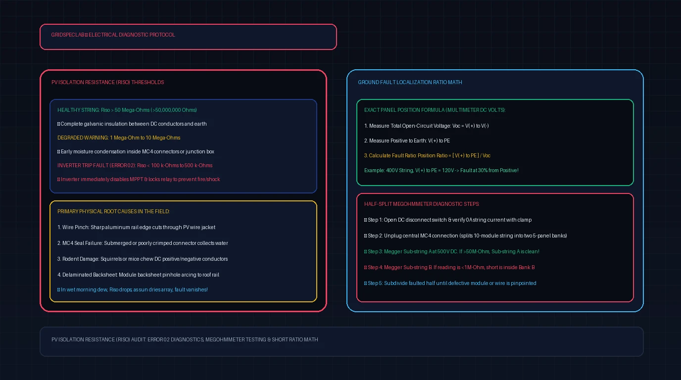
You walk into your solar mechanical room on a foggy or rainy morning, and your inverter display is glowing bright red. Instead of producing electricity, the screen flashes “Error 02”, “PV Isolation Low”, “ISO Fault”, or “Ground Fault”. By midday, as the clouds break and the sun warms the roof, the inverter clears the fault on its own and resumes normal generation—only to fail again the next wet morning.
This intermittent symptom is one of the most widespread and frustrating field challenges in residential and commercial solar installations. Modern transformerless hybrid and grid-tie inverters (including Sol-Ark, EG4, Growatt, Fronius, SMA, and Deye) feature sensitive ground fault detection interrupters (GFDI) and Residual Current Monitoring Units (RCMU). When an electrical conductor in the high-voltage PV array establishes even a microscopic conductive path to the grounded mounting rails, the inverter instantly shuts down its Maximum Power Point Trackers (MPPTs) to protect against deadly electric shocks and rooftop electrical fires.
Diagnosing a ground fault does not require dismantling every solar panel on your roof. By understanding the physics of isolation resistance, applying straightforward multimeter voltage-to-ground ratio calculations, and conducting structured high-voltage megohmmeter testing, you can isolate the exact damaged wire, pinched rail, or flooded connector quickly and safely.
Under UL 1741 and IEC 62109 safety standards, ungrounded transformerless PV arrays must maintain an insulation resistance () exceeding (or an impedance cutoff proportional to system voltage: ). When moisture, pinched conductors, or backsheet punctures drop this resistance below 100 kΩ–500 kΩ, the inverter’s internal relay locks open. Never disable the ground fault monitor or bypass earth terminals—doing so can energize the entire aluminum roof frame to 400V DC.
Anatomy of PV Isolation Resistance (Riso)
In an ungrounded DC photovoltaic array, neither the positive () nor the negative () copper conductor is connected to ground. Instead, the entire electrical circuit floats galvanically isolated from the mounting hardware, roof flashing, and earth ground.
Before an inverter closes its internal contactors to feed power into your electrical panel, it executes an automated self-test cycle. Inside the inverter, an internal measurement bridge injects an internal test bias voltage between the DC conductors and Protective Earth (PE). The micro-controller calculates the combined insulation resistance () using Ohm’s Law:
[ Solar String: Module 1 to Module 10 (350V - 500V DC) ]
       │                                     │
    ( PV+ )                               ( PV- )
       │                                     │
       ▼                                     ▼
 ┌────────────────────────────────────────────────────────┐
 │ Inverter DC Input Stage                                │
 │   • RCMU (Residual Current Monitoring Unit)            │
 │   • Internal Isolation Sensing Bridge                  │
 └──────────────────────────┬─────────────────────────────┘
                            │ (Measuring leakage current)
                            ▼
              [ Protective Earth / Ground Rod ]
Healthy vs Faulty Resistance Standards
| Array Condition | Insulation Resistance () | Inverter Response | Operating Status |
|---|---|---|---|
| New, Dry Array | () | Pass Self-Test | Normal Grid/Battery Generation |
| Humid / Morning Dew | Pass Self-Test | Normal Generation | |
| Early Degradation | Warning / Advisory | System runs, but inspection needed | |
| Moisture Ingress | Inverter Trips | Error 02 / PV Isolation Low lock | |
| Direct Metal Short | Under | Immediate Trip | High-risk dead short; zero generation |
When an array is dry, high-grade cross-linked polyethylene (XLPE) or ethylene propylene diene monomer (EPDM) insulation on 10 AWG or 12 AWG PV wire provides hundreds of mega-ohms of resistance. However, if that jacket is compromised, water acting as an electrolyte drops the resistance by multiple orders of magnitude.
Root Causes of PV Isolation Faults in the Field
Field audits demonstrate that over 90% of PV isolation errors are caused by physical installation defects rather than internal inverter component failures.
Pinched Conductors Against Racking Rails
The single most prevalent cause of PV ground faults is physical compression of cables against sharp aluminum mounting extrusions. During installation, when solar modules are tightened down with mid-clamps and end-clamps, loose wiring can become caught between the module frame and the aluminum racking rail. Over months of thermal expansion, wind flutter, and vibration, the sharp edge of the rail cuts through the outer nylon jacket and PVC insulation, placing the copper conductor in direct electrical contact with the grounded racking structure.
Water Ingress in Submerged MC4 Connectors
While standard MC4 connectors carry an IP67 or IP68 ingress protection rating, their seals rely entirely on proper assembly:
- Incorrect Cable Gland Torque: If the compression cap is hand-tightened rather than torqued with dedicated MC4 disconnect wrenches, the internal rubber ferrule fails to seal around the cable jacket.
- Connectors Resting in Roof Valleys: Installers who fail to zip-tie cables to module frames often leave connectors resting directly on shingles or in roof valleys. During heavy rainstorms, pooling water submerges the connector. Capillary action draws water into the mating pin, creating a low-resistance path to earth.
- Cross-Mated Brands: Mating an original Multi-Contact (Stäubli) MC4 with a generic clone (often called “MC4-compatible”) frequently results in microscopic dimensional gaps around the silicone O-ring, leading to persistent moisture intrusion.
Rodent and Pest Damage
Squirrels, raccoons, and birds nesting under solar arrays often gnaw through PV wire insulation. Squirrels have continuously growing incisors and frequently strip several inches of jacket down to bare stranded copper. In dry conditions, the air gap may be large enough to prevent an electrical arc, but when morning mist covers the roof, the moisture bridges the bare copper to the grounded roof deck.
Backsheet Delamination and Micro-Cracks
Older or budget solar modules manufactured with substandard polyamide-based backsheets (such as certain vintage modules using defective film blends) suffer from severe backsheet cracking after 5 to 8 years of ultraviolet exposure. Micro-cracks along the busbars allow water to seep directly into the electrified silicon wafers and tinned copper ribbons, shorting the internal circuit to the aluminum frame.
Pinpointing the Fault: Voltage-to-Ground Ratio Math
Before climbing onto the roof with ladders and safety harnesses, you can calculate the exact physical location of the ground fault from the safety of your ground-level inverter disconnect box using a standard high-impedance Digital Multimeter (DMM).
When an isolated DC string develops a ground fault, the short acts as an unintentional center-tap or voltage divider relative to earth ground. By measuring the open-circuit voltage from both positive and negative poles to ground, the ratio reveals how many modules away the short is located.
       Module 1      Module 2      Module 3 (FAULT)    Module 4      Module 5
    ┌───────────┐ ┌───────────┐ ┌───────────┐ ┌───────────┐ ┌───────────┐
(+) ┤           ├─┤           ├─┤  *PINCH*  ├─┤           ├─┤           ├ (-)
    └───────────┘ └───────────┘ └─────┬─────┘ └───────────┘ └───────────┘
                                      │ (Short to Rail)
                                      ▼
                            === GROUND (0V PE) ===
Step-by-Step Multimeter Ratio Procedure
- Shut Down the Inverter: Turn off the inverter AC breaker and switch the DC disconnect to the OFF position.
- Verify Zero Current: Use a DC clamp meter around the positive and negative PV leads to confirm that zero amperes () are flowing.
- Measure String Open-Circuit Voltage (): Place your multimeter leads across and . Record this value (e.g., ).
- Measure Positive to Ground (): Place the red probe on and the black probe on the inverter’s chassis ground / Protective Earth busbar. Record the voltage.
- Measure Negative to Ground (): Place the red probe on and the black probe on ground. Record the voltage.
The Mathematical Ratio Formula
In an ideal floating array with zero faults, your multimeter will show an unstable, decaying ghost voltage (often floating near half the string voltage due to internal high-impedance bleeder resistors).
However, if a true ground fault exists, the readings will be solid and stable, and their absolute values will sum to the total string open-circuit voltage:
To calculate the exact module position of the fault starting from the positive string terminal, use the Fault Location Ratio:
To find the specific module index () in a series string containing identical modules:
Real-World Field Diagnostic Example
Assume you have a string of 10 modules, each rated for an open-circuit voltage () of .
- Measured String :
- Measured :
- Measured :
Apply the formula:
Multiply by the 10 modules:
The Diagnostic Finding: The ground fault is located precisely 3 modules down from the positive home run cable, at the junction between Module 3 and Module 4! Instead of unbolting 10 solar modules, you can go directly to Module 3 on the roof, inspect its outgoing cable, and find the pinched wire or flooded connector immediately.
High-Voltage Insulation Testing: The Megohmmeter Protocol
While a standard multimeter measuring voltage-to-ground works well for dead shorts, it often fails on “dry-weather intermittent” faults. A standard handheld multimeter only outputs 3V to 9V from its internal battery to test resistance. A microscopic nick in a cable jacket will easily resist 9V, but the moment the solar array reaches its operating voltage of 350V to 500V DC, the voltage breaks down the air gap and arcs to ground.
To find high-resistance insulation breakdowns, professional solar technicians use a Megohmmeter (Insulation Resistance Tester, such as a Fluke 1507 or Megger MIT400).
   ┌────────────────────────────────────────────────────────┐
   │ MEGOHMMETER (Set to 500V or 1,000V DC Insulation Test) │
   └───────────────┬────────────────────────┬───────────────┘
                   │ (+) Red Probe          │ (-) Black Probe
                   ▼                        ▼
       [ Shorted PV+ / PV- Lead ]    [ Ground Rail / Earth PE ]
                   │                        │
                   └────── Array Test ──────┘
[!WARNING] High Voltage Shock Hazard A megohmmeter injects 500V to 1,000V DC onto the circuit during testing. Never touch bare conductors or connectors while the test button is depressed. Ensure all personnel are clear of the solar array before initiating an insulation test.
Pre-Test Safety Checklist
- Disconnect from Inverter: Unplug both and cables from the inverter terminals. Never apply 1,000V from a megohmmeter into an inverter’s MPPT input—doing so will instantly destroy the inverter’s sensitive input capacitors and surge diodes.
- Short to Together: In accordance with IEC 62446 commissioning standards, during a high-voltage insulation test of a live PV array in daylight, the positive and negative string cables should be securely bonded together using a rated jumper or breaker. This ensures that the high-voltage test impulse stresses the external insulation to ground rather than forcing test current through the solar cell bypass diodes.
- Verify Zero Current: Ensure the string disconnect is fully open before applying test leads.
Megohmmeter Test Voltages by System Voltage Rating
| Maximum Array DC Voltage () | Recommended Megger Test Voltage | Minimum Passing Resistance | Target Quality Standard |
|---|---|---|---|
| Up to 150V DC (Off-Grid 48V setups) | 250V DC | ||
| 150V to 600V DC (Residential String) | 500V DC | ||
| 600V to 1,000V DC (Commercial Arrays) | 1,000V DC |
Connect the positive (red) megohmmeter lead to the bonded jumper, and connect the negative (black) megohmmeter lead to the bare metal equipment grounding conductor (EGC) or aluminum racking rail (ensuring your alligator clip penetrates any anodized aluminum coating). Press and hold the test button for 60 seconds to allow capacitive charging current to settle. A reading under confirms an active insulation fault.
The Half-Split Isolation Technique
When inspecting large residential strings (12 to 16 modules) or commercial rooftop arrays where the exact ground fault ratio is ambiguous, the most efficient physical method to isolate the short is the Half-Split Method (Binary Search).
Instead of disconnecting modules one by one, you divide the string in half at each step. This allows you to pinpoint the fault in just 3 to 4 test cycles.
Initial 16-Panel String:
[1] [2] [3] [4] [5] [6] [7] [8]  |  [9] [10] [11] [12] [13] [14] [15] [16]
            ▲                    │
     (FAULT IN PANEL 3)          │ Disconnect MC4 at Panel 8/9
                                 ▼
Sub-String A (Panels 1-8): FAILS TEST (under 100kΩ) ──► Keep bisecting
Sub-String B (Panels 9-16): PASSES TEST (>100MΩ) ──► Fully cleared!
Execution Steps for the Half-Split Method
- Split the String in Half: For a 16-module string, climb to the roof and disconnect the series MC4 jumper between Module 8 and Module 9. You now have two isolated sub-strings:
- Sub-String A: Modules 1 through 8
- Sub-String B: Modules 9 through 16
- Test Sub-String A: Connect your insulation tester between the positive lead of Module 1 and ground.
- If the resistance is , Sub-String A is completely healthy.
- If the resistance drops below , the fault is trapped inside Modules 1 through 8.
- Test Sub-String B: Connect your tester between the negative lead of Module 16 and ground.
- Bisect the Faulty Sub-String: If Sub-String A failed, disconnect the jumper between Module 4 and Module 5. Test Modules 1–4 and Modules 5–8.
- Pinpoint the Module: Within 4 splits, you isolate the single 2-module section containing the chafed wire, wet junction box, or pinched cable.
Permanent Repairs and Preventative Standards
Once the ground fault has been physically identified, executing a compliant, weather-tight repair is critical to ensure the fault does not recur during the next rainy season.
How to Properly Repair Chafed PV Wire
Never wrap damaged high-voltage DC solar wire in standard hardware-store vinyl electrical tape. Over time, roof temperatures exceeding 140°F (60°C) and direct UV rays will melt the adhesive, causing the tape to unwrap and re-expose the conductor.
- Option A (The Professional Standard): Replace the entire jumper cable or wire run from connector to connector with fresh 10 AWG or 12 AWG cross-linked polyethylene (USE-2 or UL 4703 rated) PV wire.
- Option B (In-Line Waterproof Splice): If replacing the wire requires cutting into the module junction box, cut out the damaged copper section, install a dual-wall, adhesive-lined polyolefin heat-shrink sleeve over the cable, crimp an insulated butt splice with a calibrated ratcheting tool, slide the heat shrink over the joint, and heat until adhesive oozes from both ends to form a 100% submersible seal.
Cable Management Best Practices
To prevent mechanical damage from wind abrasion and thermal movement:
- Use Stainless Steel 304/316 PV Cable Clips: Secure all wiring directly to the module return lips. Never allow cables to sag and touch abrasive asphalt shingles or sharp tile edges.
- Avoid 90-Degree Rail Bends: Maintain a minimum bend radius of at least 5 times the cable outer diameter (typically around 1.5 to 2.0 inches). Never bend PV wire tightly over the end of an aluminum rail.
- Support Connectors Horizontally: Position all MC4 connectors tucked up underneath the glass surface of the solar module, oriented horizontally or slightly downward so rainwater drains off the shell rather than pooling in the cable boot.
Diagnostic Flowchart for Field Technicians
Follow this systematic decision tree whenever an inverter reports PV Isolation Low or Ground Fault Error 02:
                  [ Inverter Displays Error 02 / ISO Low ]
                                    │
                                    ▼
                 [ Shut Down AC & DC Disconnect Switches ]
                                    │
                                    ▼
             [ Measure Voc and V(+) to Ground / V(-) to Ground ]
                                    │
              ┌─────────────────────┴─────────────────────┐
              ▼                                           ▼
      [ Stable Voltage Ratio ]                   [ Unstable / Floating ]
              │                                           │
              ▼                                           ▼
   Calculate Fault Module:                       Perform Megohmmeter Test
   Ratio = V(+) / Voc                            at 500V DC (Wet Test)
              │                                           │
              ▼                                           ▼
   Go directly to calculated                    Apply Half-Split Technique:
   panel index on rooftop                       Disconnect string at midpoint
              │                                           │
              └─────────────────────┬─────────────────────┘
                                    │
                                    ▼
           [ Visually Inspect Wiring, MC4s, and Rail Clamps ]
                                    │
                                    ▼
         [ Replace Damaged Wire / Secure Stainless Cable Clips ]
                                    │
                                    ▼
           [ Retest with Megger: Confirm Riso > 50 Mega-Ohms ]
                                    │
                                    ▼
               [ Restore Inverter Power: Normal Generation ]
Frequently Asked Questions
Why does my PV isolation error disappear in the afternoon?
During the night and early morning, high humidity, dew, and morning fog cause water to condense onto the array. If a connector has a loose seal or a wire has a minor nick, this moisture bridges the gap between the copper conductor and the grounded roof frame, lowering the resistance below the inverter’s safety cutoff. As the sun rises, solar irradiance heats the panels to 110°F–140°F, evaporating the moisture and raising the resistance back above . The fault will inevitably return during the next rainstorm until the damaged insulation is repaired.
Can a faulty inverter cause an Error 02 code when the array is fine?
Yes, though it accounts for less than 5% of field occurrences. Inverters utilize internal metal oxide varistors (MOVs) and surge protection circuits connected between DC input terminals and ground. If a nearby lightning strike or grid surge degrades an internal MOV, it may begin leaking current to the inverter’s chassis ground. To verify this, disconnect all PV string connectors from the inverter inputs and run an internal isolation self-test. If the inverter still reports Error 02 with zero cables plugged into its DC inputs, the internal isolation sensing circuit or surge board has failed and requires service.
Will a ground fault cause a solar rooftop fire?
If left unaddressed, yes. An isolation fault represents an unintended electrical path to ground. In high-voltage DC systems (300V to 600V DC), a partial ground fault combined with poor racking bonding can establish a sustained direct-current plasma arc. Unlike AC power, which crosses zero voltage 120 times per second and self-extinguishes, DC arcs do not self-extinguish and burn at temperatures exceeding 5,000°F (2,800°C), capable of igniting roofing materials. The inverter’s isolation shutoff is a vital life-safety feature designed to prevent precisely this disaster.
Conclusion
A solar PV isolation error is not a mystery—it is a measurable electrical condition that protects your home and equipment from dangerous ground leakage. By setting aside guesswork and applying the voltage-to-ground ratio formula, you can pinpoint the exact module in the series string where the fault has occurred. Backed by high-voltage megohmmeter verification and durable, UV-resistant repair standards, you can permanently clear Error 02 and restore continuous, safe solar energy production to your system.