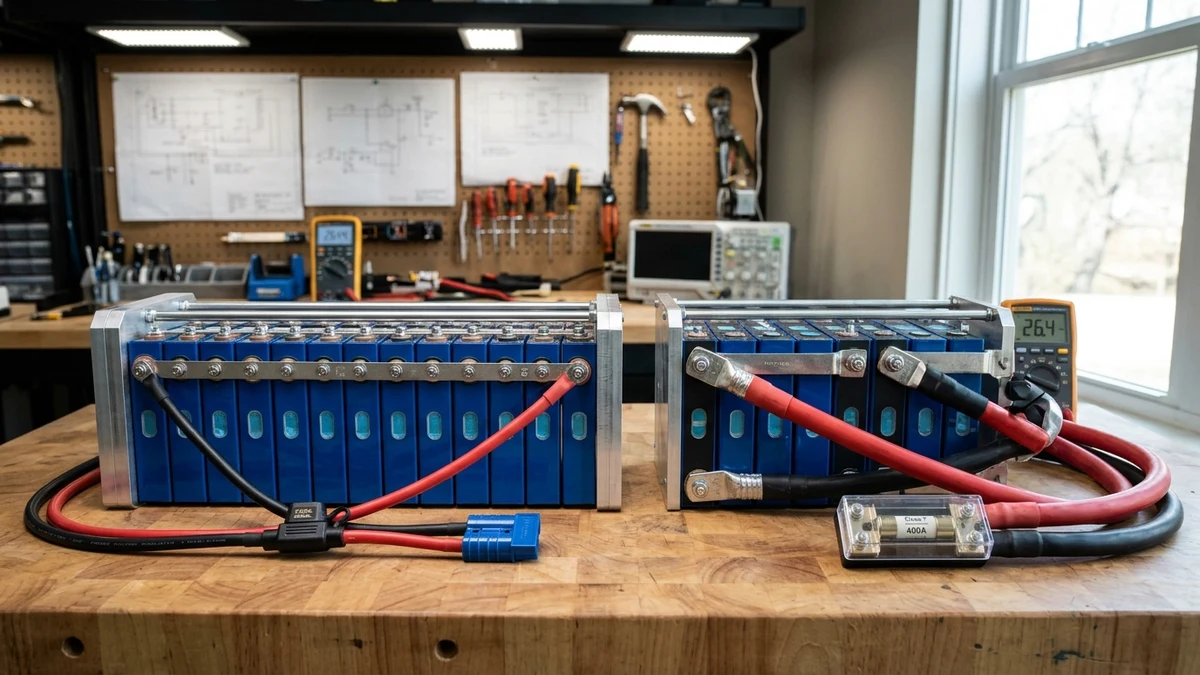
When designing a DIY lithium iron phosphate (LiFePO4) energy storage system, builders face a pivotal architectural fork in the road: should you wire your prismatic cells in an 8-cell series string (8S, nominal 25.6V) or step up to a 16-cell series string (16S, nominal 51.2V)?
Historically, 24-volt systems occupied a comfortable middle ground between legacy 12V automotive setups and high-voltage commercial microgrids. However, as residential power demands have grown—driven by modern induction cooktops, well pumps, workshop air compressors, and mini-split heat pumps—the electrical physics of low-voltage DC transmission has shifted decisively in favor of 48-volt architectures.
In this first-principles electrical engineering analysis, the GridSpecLab hardware team breaks down the mathematics of conductor sizing, resistive heat dissipation ( losses), inverter efficiency curves, BMS balancing overhead, and total bill-of-materials cost comparing 8S and 16S battery configurations.
If your maximum continuous inverter draw is under 2,000 Watts (such as in a camper van or small truck camper), an 8S (24V) battery pack offers compact simplicity. For any installation exceeding 2,000 Watts continuous or 4,000Wh total capacity—including off-grid cabins, workshops, and whole-home backup—a 16S (48V) architecture delivers superior thermal efficiency, 75% lower resistive line loss, drastically cheaper copper wiring, and native compatibility with modern hybrid inverters.
Browse 48V Server Rack Batteries →
The Mathematical Physics of System Voltage: Ohm’s Law and Thermal Losses
The fundamental advantage of 16S over 8S stems directly from the laws of classical electrodynamics. Power (), expressed in Watts, is the mathematical product of electromotive potential () in Volts and electrical current () in Amperes:
When you double the system voltage from a nominal (8S LiFePO4) to (16S LiFePO4) to deliver an identical quantity of electrical power, the operating current is reduced by exactly 50%.
Now consider Joule’s Law of resistive heating, which dictates the rate at which electrical energy is converted into unwanted thermal heat inside copper conductors, terminal lugs, busbars, and BMS circuit traces:
Because current () is squared in the loss equation, halving the current does not merely halve the heat loss—it slashes power dissipation by a factor of four ():
To demonstrate this in practical off-grid terms, observe how a continuous 3,000-Watt appliance load (such as a central well pump and kitchen microwave running concurrently) stresses both systems across a 10-foot round-trip DC cable run with an equivalent loop resistance of :
- 8S Configuration (): Pulls . Power lost to cable heat equals .
- 16S Configuration (): Pulls . Power lost to cable heat equals .
Over an entire day of continuous battery cycling, that difference translates into kilowatt-hours of solar energy converted into warm ambient heat rather than powering your household loads.
Conductor Sizing and Ampacity: Comparing Copper Thickness
In low-voltage DC systems, conductor selection is governed by two constraints mandated by the National Electrical Code (NEC Article 690 / Article 705): conductor ampacity ratings and maximum permissible voltage drop ().
High Amperage Reality of Lower Voltage Systems
When sizing DC cables, higher currents require dramatically thicker copper gauges. Consider continuous loads ranging from 2,000 Watts to 6,000 Watts:
| Inverter Continuous Load | 24V System Amperage (8S @ 25.6V) | 24V Minimum Cable Gauge (NEC 90°C) | 48V System Amperage (16S @ 51.2V) | 48V Minimum Cable Gauge (NEC 90°C) |
|---|---|---|---|---|
| 2,000 Watts (Small Cabin) | 78.1 Amperes | 4 AWG Copper | 39.1 Amperes | 8 AWG Copper |
| 3,000 Watts (Standard Homestead) | 117.2 Amperes | 1/0 AWG Copper | 58.6 Amperes | 4 AWG Copper |
| 4,000 Watts (Split-Phase Well Pump) | 156.3 Amperes | 3/0 AWG Copper | 78.1 Amperes | 2 AWG Copper |
| 6,000 Watts (Whole-Home Backup) | 234.4 Amperes | 4/0 AWG Copper (or Dual 2/0) | 117.2 Amperes | 1/0 AWG Copper |
| 12,000 Watts (Heavy Workshop / HVAC) | Impractical () | Requires 4x 4/0 Runs | 234.4 Amperes | 4/0 AWG Copper Single Run |
Copper Cross-Sectional Area and Voltage Drop
Voltage drop across a direct current circuit is calculated as:
Where is one-way cable length in feet, and is conductor resistance per foot.
In a 24V system, losing just across battery cables represents a voltage drop, which can trigger premature low-voltage inverter alarms during heavy inductive surges. In a 48V system, that same drop represents only , comfortably within optimal engineering parameters.
Furthermore, routing stiff, heavy 4/0 AWG welding cable inside tight battery cabinets requires massive bend radiuses (), straining terminal studs and complicating conduit routing. A 48V system allows slim, flexible 2 AWG or 4 AWG conductors that route effortlessly through standard knockouts.
Inverter Efficiency Curves and Tare Idle Consumption
The internal topology of modern off-grid inverters is fundamentally optimized for 48-volt DC buses.
To convert direct current into 120V or 240V split-phase alternating current, inverters utilize high-speed MOSFET or IGBT switching bridges paired with either a high-frequency ferrite transformer or a massive low-frequency toroidal transformer:
- Voltage Multiplication Factor: Stepping up to a peak AC sine wave voltage of (for 120VAC RMS) or (for 240VAC RMS) requires a voltage multiplication factor of . Stepping up from requires only a multiplication.
- Internal Transistor Current: Lower primary voltage forces internal power transistors to switch double the amperage. High-current MOSFET conduction losses degrade peak conversion efficiency by .
- Idle Consumption (Tare Loss): Because 48V inverters switch lower primary current, they utilize smaller filter inductors and lower-capacitance bus filters, reducing parasitic tare losses relative to output capacity.
| Inverter Model & Architecture | System Voltage | Peak Conversion Efficiency | CEC Weighted Efficiency | Continuous AC Output |
|---|---|---|---|---|
| Victron MultiPlus-II 24/3000 | 24V DC (8S) | 94.0% | 91.5% | 2,400 Watts |
| Victron MultiPlus-II 48/5000 | 48V DC (16S) | 96.0% | 94.5% | 4,000 Watts |
| EG4 6000XP Off-Grid Inverter | 48V DC (16S) | 95.0% | 93.5% | 6,000 Watts |
| Growatt SPF 3000TL LVM-24P | 24V DC (8S) | 90.0% | 88.5% | 3,000 Watts |
| Growatt SPF 5000ES Inverter | 48V DC (16S) | 93.0% | 92.0% | 5,000 Watts |
| Sol-Ark 15K Whole-Home Hybrid | 48V DC (16S) | 96.5% | 95.0% | 12,000 Watts (Split-Phase) |
Notice that the industry’s most advanced all-in-one hybrid inverters—such as the Sol-Ark 15K, EG4 18kPV, and Fortress Envy—do not even exist in 24V variants. The maximum practical limit for a 24V inverter is 3,000 Watts; exceeding 3kW requires a 48V architecture.
Battery Management System Complexity: Eight Cells vs Sixteen Cells
A frequent argument raised by advocates of 24-volt systems is that an 8S battery configuration is simpler to assemble and manage than a 16S battery pack. While mathematically true regarding cell count, the practical operational trade-offs tell a different story.
Balancing Overhead and Wiring Count
- 8S Configuration: Requires eight prismatic cells, seven inter-cell busbars, and nine balance lead wires ( through ). Top-balancing eight cells takes approximately half the bench time of sixteen cells.
- 16S Configuration: Requires sixteen prismatic cells, fifteen inter-cell busbars, and seventeen balance lead wires ( through ).
However, modern smart BMS units—including the JK Smart Active Balancer BMS and the Seplos Mason 200A BMS—feature high-current active balancing (). These active circuits automatically redistribute charge from high-voltage cells to lagging cells, rendering the perceived balancing complexity of sixteen cells a non-issue during daily operation.
Closed-Loop Protocol Availability and Inverter Interfacing
In the current solar market, virtually all commercial closed-loop battery communication standards (CAN-bus and RS485 protocols like Pylontech, Victron CAN, and EG4 protocol) are designed around 48-volt 15S/16S battery architecture:
- Connecting a 48V 16S DIY battery pack to an inverter allows the BMS to actively command the inverter’s charge voltage, charge current limit (CCL), and discharge current limit (DCL) over a standard RJ45 cable.
- 24V DIY systems are frequently relegated to open-loop “lead-acid” voltage settings, requiring manual tuning of absorption, float, and low-voltage cutoff voltages without automated cell-level safety throttling.
Component Cost Breakdown: Copper, Class T Fusing, and Charge Controllers
While sixteen raw 280Ah cells cost exactly double eight raw 280Ah cells, the surrounding balance-of-system electrical hardware tells the exact opposite financial story.
Consider the cost to equip both systems for a 3,000-Watt continuous inverter:
| Electrical Balance of System Hardware | 24V System Hardware (8S String) | 48V System Hardware (16S String) | Cost Variance / Savings |
|---|---|---|---|
| Main DC Battery Cables (10ft 4/0 vs 2 AWG) | $145 (4/0 AWG Fine Strand Copper) | $48 (2 AWG Fine Strand Copper) | $97 Saved at 48V |
| Main Overcurrent Protection (Class T Fuse) | $85 (300A Class T Block + Fuse) | $62 (150A Class T Block + Fuse) | $23 Saved at 48V |
| Main Battery Disconnect Breaker | $110 (250A High-AIC DC Breaker) | $65 (125A High-AIC DC Breaker) | $45 Saved at 48V |
| Solar MPPT Charge Controller (3,000W Solar PV) | $580 (Dual 60A 24V MPPTs or 100A unit) | $290 (Single 60A 48V MPPT Controller) | $290 Saved at 48V |
| Copper Busbars & Lugs | $65 (Large 4/0 Compression Lugs) | $28 (Standard 2 AWG Lugs) | $37 Saved at 48V |
| Total Balance of System Cost | $985 | $493 | $492 Saved at 48V |
Notice the dramatic saving on the Solar MPPT Charge Controller:
- A charge controller is rated by its maximum output current to the battery.
- To harvest 3,000 Watts of rooftop solar array into a 24V battery bank: . This requires an expensive, massive 100A+ MPPT controller or two separate 60A units wired in parallel.
- To harvest that same 3,000 Watts into a 48V battery bank: . A single standard 60A MPPT controller handles the entire solar array effortlessly.
Practical Application Decision Matrix: Cabins, RVs, and Workshops
To make the definitive choice between an 8S and 16S battery build, evaluate your installation against these operational criteria:
Mobile Van Life and Compact RV Installations
- When 8S (24V) Excels: If your mobile build already utilizes a 24V DC alternator charger (such as a Nations dual alternator) or native 24V DC air conditioning (like a Nomadic Cooling or Mabru 24V rooftop unit), and your total daily inverter demand is limited to small appliances (induction burner, laptop charging, Starlink), an 8S pack saves space and matches chassis weight limits.
- Limitations: Adding a second battery pack requires parallel strings, and stepping down to 12V for interior LED puck lights, water pumps, and USB outlets requires heavy-duty 24V-to-12V DC-DC buck converters.
Off-Grid Homesteads, Workshops, and Whole-Home Storage
- When 16S (48V) Is Mandatory: For any stationary building, cabin, or homestead where you plan to run standard residential appliances (central air conditioning, clothes dryers, deep well pumps, table saws, electric vehicle charging), 16S is the only logical choice.
- Scalability: 48V server rack standards allow you to start with one 16S pack (14.3kWh) and cleanly parallel up to thirty-two identical packs (over 450kWh of storage) without upgrading your inverter DC bus cables or melting disconnect switches.
Frequently Asked Questions About Battery System Voltages
Can I build two 8S 24V batteries and wire them in series to make 48V?
While electrically possible, wiring two separate 8S batteries in series to create a 48V bank is a poor engineering choice. Each 8S pack has an independent BMS with internal MOSFET disconnect switches. If one BMS trips on cell over-voltage while charging, the entire 48V circuit opens abruptly, exposing the tripped BMS MOSFETs to the full 51V voltage potential across its open contacts, which can cause semiconductor punch-through and destroy the BMS. If you want 48V, always build a native 16S single-BMS battery pack.
Is 48V DC dangerous compared to 24V DC?
Under OSHA electrical safety standards and the National Electrical Code, direct current voltages under 60 Volts DC are classified as “Extra-Low Voltage” (Class 2 touch-safe), meaning dry human skin contact does not present a lethal shock hazard under normal operating conditions. However, high-amperage short circuits from either 24V or 48V lithium batteries can produce catastrophic arc flashes and vaporize metal tools. Always wear safety glasses, use insulated wrenches, and install a fast-acting Class T fuse immediately adjacent to the battery positive terminal.
What happens if I want to run 12V DC appliances from a 48V battery?
High-efficiency 48V-to-12V DC-DC converters (such as Victron Orion-Tr isolated converters) operate at 95% efficiency, cleanly stepping down 48V to stable 13.8V DC to power marine bilge pumps, RV lighting, diesel heaters, and cellular routers without draining individual cells unevenly.