Diverting surplus photovoltaic generation into domestic water heating is one of the most cost-effective methods to maximize the return on investment of an off-grid solar installation. Once a lithium battery bank reaches its float charge threshold, rather than letting solar panels sit idle in curtailment, an automated energy diverter routes excess DC power into an electric water heating element.
However, switching high-current direct current (DC) introduces severe electrical hazards that catch many renewable energy builders unprepared.
In alternating current (AC) circuits, line voltage naturally passes through zero volts 120 times every second (at 60Hz). When mechanical switch contacts pull apart, this periodic zero-crossing naturally de-ionizes the air gap and extinguishes electrical arcs automatically.
Direct current possesses no zero-crossing. When opening a live 48V, 72V, or 120V DC circuit carrying 20 to 30 Amperes of current, the electrical energy ionizes the surrounding air into an intense, persistent plasma arc exceeding 5,000°F (2,760°C). Standard AC relays and household light switches will literally weld their contacts shut or vaporize into flames within a few dozen operational cycles.
To automate DC water heating reliably, engineers select between two distinct electrical control technologies:
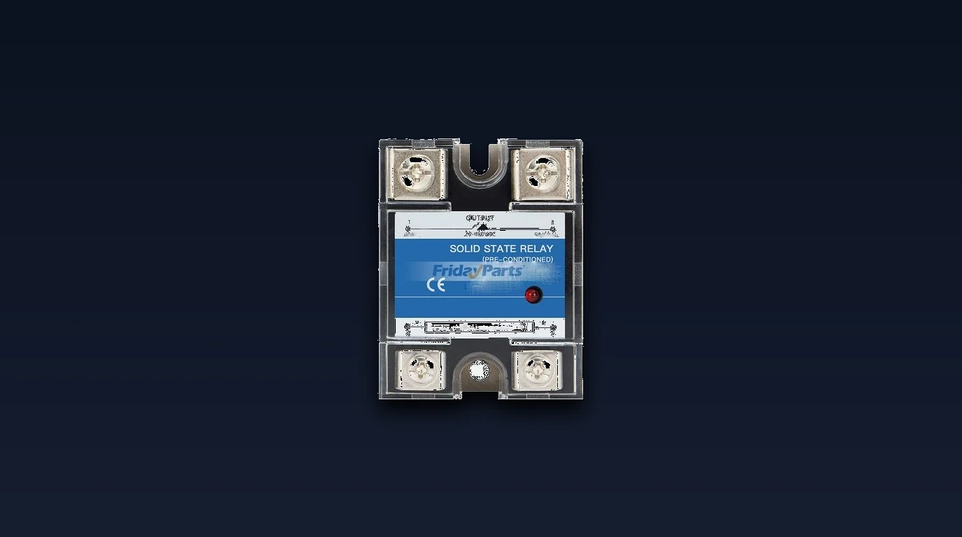
- The DC Solid-State Relay (SSR): A semiconductor-based switch utilizing power MOSFETs or IGBTs with zero moving parts, silent operation, and infinite cycle life.
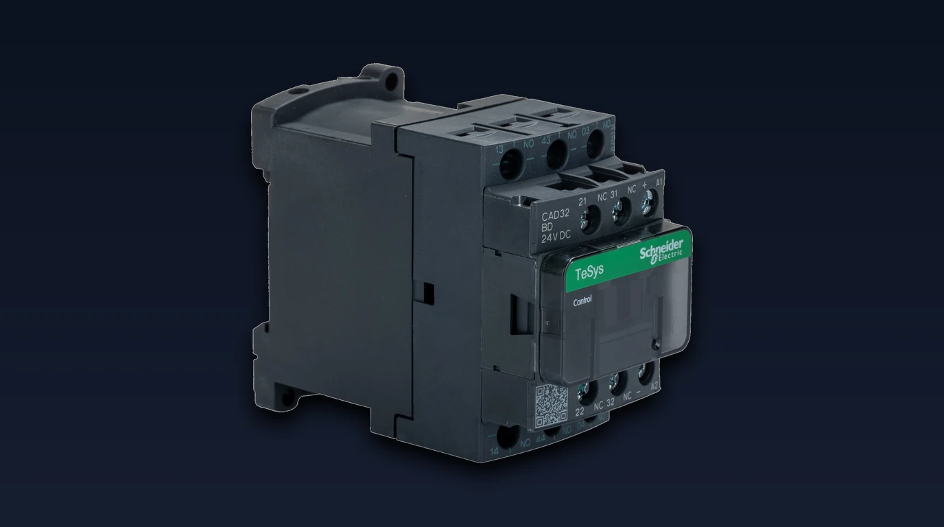
- The Mechanical DC Contactor: A heavy-duty electromechanical switch incorporating specialized magnetic blowouts and wide air gaps to physically deflect and extinguish DC plasma arcs.
This engineering comparison audits the physics of DC arc suppression, measures semiconductor thermal losses, outlines heatsink sizing math, and details critical safety interlocks required to prevent thermal runaway.
Executive Summary: The DC Arc Suppression Dilemma
+-----------------------------------------------------------------------------------+
|                        DC SWITCHING ARCHITECTURE OVERVIEW                         |
+-----------------------------------------------------------------------------------+
|  Architecture A: DC Solid-State Relay (Crydom D1D40 on Extruded Heatsink)         |
|  [ Microcontroller / PWM Signal ] ---> [ Optocoupler ] ===> [ Power MOSFET Array ] |
|  • Infinite mechanical switching life; supports high-frequency PWM modulation      |
|  • Silent operation; zero acoustic clicking during rapid solar tracking           |
|  • Substantial forward voltage drop (1.2V - 1.6V) generating severe internal heat |
|  • High failure risk: almost always fails into a PERMANENT SHORT-CIRCUIT!         |
+-----------------------------------------------------------------------------------+
|  Architecture B: Mechanical DC Contactor (Schneider Electric TeSys with Blowout)  |
|  [ 12V/24V Control Relay ] ---> [ Magnetic Solenoid Coil ] ===> [ Silver Contacts] |
|  • Near-zero electrical resistance; completely cold running (0 Watts heatsink loss)|
|  • Fails open safely when control power is lost                                   |
|  • Audible mechanical clunk; limited contact lifespan (100k - 250k cycles)        |
|  • Unsuitable for PWM throttling; restricted to bulk ON/OFF cycling               |
+-----------------------------------------------------------------------------------+
Physics of Direct Current Switching: Arc Quenching and Contact Erosion
To appreciate why conventional relays fail on DC water heating circuits, one must examine the plasma physics of contact separation:
       +-------------------------------------------------------------+
       |             THE SUSTAINED DIRECT CURRENT ARC                |
       +-------------------------------------------------------------+

          48V DC Line In o-----+
                               |
                               v
                     [ Moving Mechanical Contact ]
                               |
                               |  <--- 5,000°F Plasma Arc Sustained
                               |       (No Zero Crossing to Quench)
                               |
                               v
                     [ Stationary Contact Pad ]
                               |
                               v
                     [ To Water Heating Element ]
When mechanical contacts separate under inductive or high-amperage resistive DC loads:
- As the contact points move microns apart, current density concentrates across the final metallic asperities.
- The extreme local heat boils the silver or copper metal, emitting free electrons via thermionic emission.
- The surrounding air gas molecules ionize into a conductive plasma channel.
- Because DC voltage is continuous, current continues to flow through the plasma bridge even across an air gap of several millimeters.
- The molten contact surfaces splash together, permanently welding the contacts closed—a catastrophic failure mode detailed in our guide to DC thermostat arc welding.
DC Solid-State Relays: Semiconductor Architecture and Forward Voltage Drop
DC Solid-State Relays (such as the Crydom D1D40 or Sensata Series 1-DC) replace mechanical contacts with a parallel array of high-current power MOSFETs (for systems under 100V DC) or IGBTs (for high-voltage direct PV arrays).
+-----------------------------------------------------------------------------------+
|                        DC SOLID-STATE RELAY INTERNAL SCHEMATIC                    |
+-----------------------------------------------------------------------------------+
|                                                                                   |
|  Low-Voltage Input (3-32V DC) ---> [ Opto-Isolator LED ]                          |
|                                                | (Photons)                        |
|                                                v                                  |
|                                    [ Photovoltaic Driver IC ]                     |
|                                                |                                  |
|                                                v                                  |
|  DC High-Power Line In (+) --------> [ Parallel Power MOSFETs ]                   |
|                                                | (R_DS(on) Resistance)            |
|                                                v                                  |
|  Load Output to Water Heater <-----------------+                                  |
|                                                                                   |
+-----------------------------------------------------------------------------------+
The Benefits of Solid-State Switching
- Infinite Switching Cycles: Because there are no springs, armatures, or contact points to pit, an SSR can cycle millions of times without degradation.
- Compatibility with Pulse Width Modulation (PWM): An SSR can switch on and off tens or hundreds of times per second (e.g., at 100Hz). This allows solar charge controllers to proportionally throttle diversion power: matching water heater element draw precisely to excess solar wattage in real time.
- Complete Electrical Isolation: Optical coupling provides over 4,000V of galvanic isolation between the low-voltage logic controller and the high-power battery circuit.
The Thermal Penalty: Forward Voltage Drop
The fatal limitation of semiconductor switching is internal silicon resistance ( or saturation voltage drop ):
- When fully saturated, current passing through the internal silicon junctions experiences a continuous voltage drop of 1.2 to 1.8 Volts DC.
- Unlike mechanical contacts whose resistance is measured in milliohms, an SSR converts a portion of the passing power directly into heat.
Mechanical DC Contactors: Magnetic Blowouts and Low Resistance
Industrial mechanical DC contactors (such as the Schneider Electric TeSys D series, Albright SW series, or Gigavac sealed contactors) solve the thermal dissipation issue by maintaining traditional metallic contact pads.
       +-------------------------------------------------------------+
       |             MAGNETIC BLOWOUT ARC SUPPRESSION                |
       +-------------------------------------------------------------+

                         Permanent Magnet (North Pole)
                                    [ N ]
                                      |
         Contact (-) o---[ Arc Plasma Deflected Upward ]---> o Contact (+)
                                      |
                                    [ S ]
                         Permanent Magnet (South Pole)
                                      |
                                      v
                       [ Arc Chute Copper Splitter Plates ]
                         (Stretches, Cools, and Snaps Arc)
The Magnetic Blowout Mechanism
To extinguish direct current arcs without waiting for a zero-crossing:
- Rare-earth permanent magnets are positioned on either side of the contact gap.
- Under the Lorentz Force Law (), the magnetic field exerts a lateral force on the moving charged particles of the plasma arc.
- The arc is physically pushed outward into an arc chute lined with copper splitter plates.
- The splitter plates divide the single long arc into multiple tiny arcs, cooling the plasma below its ionization temperature and snapping the circuit open in under 20 milliseconds.
The Operational Advantages of Mechanical Contactors
- Zero Thermal Runaway: Total contact resistance is under . Forward voltage drop is negligible (under 0.05V). The contactor body remains completely cold under a continuous 30A load.
- Zero Heatsink Requirement: Mounts directly on standard DIN rail inside compact plastic enclosures without ventilation fans.
- Fail-Open Default: If control power is interrupted or the operating coil burns out, return springs immediately pull the contacts apart, safely de-energizing the water heater.
Thermal Dissipation and Heatsink Sizing for High-Current Solid-State Relays
The single most common installation error with DC Solid-State Relays is failing to engineer an adequate thermal dissipation pathway.
Calculating Thermal Power Dissipation
The thermal wattage () generated inside an SSR is calculated directly from load current and forward voltage drop:
Consider a standard 48V 1,200-watt immersion element drawing 25 Amperes through an SSR with an internal forward drop of 1.4 Volts:
Dissipating 35 watts of concentrated thermal energy from a tiny 2-inch by 1.7-inch epoxy baseplate requires a heavy, extruded aluminum heatsink.
Heatsink Temperature (°C)
  120 +                                           * (Thermal Runaway / Destruction)
  100 |                                          /
   80 |                                         /  (Undersized Heatsink: 3.0°C/W)
   60 |                                        /
   40 |                         *-------------*    (Proper Extruded Heatsink: 1.2°C/W)
   20 +-------------------------*-----------------------------------------------+
      0A                       10A                      20A                     30A
                                        Load Current (Amperes)
Sizing the Aluminum Heatsink
The maximum allowable heatsink thermal resistance ( in ) is determined by the formula:
Where:
- (Maximum internal MOSFET silicon junction temperature).
- (Worst-case ambient temperature inside an electrical utility box).
- (Junction-to-case internal thermal resistance).
- (Thermal interface resistance using zinc oxide thermal grease).
Engineering Rule of Thumb: An off-grid builder running 20A to 30A DC through an SSR must select an extruded aluminum heatsink rated for or lower (typically a finned aluminum block weighing at least 1.2 pounds, measuring 4” x 5” x 3”). Mounting an SSR directly to a plywood wall or the flat steel backplate of an enclosure will destroy the semiconductor within forty minutes.
The Catastrophic Semiconductor Failure Mode: Why Mechanical Lockouts Are Mandatory
When a mechanical contactor fails at the end of its operational lifespan, the failure is almost always fail-open: a return spring weakens, the coil burns out, or carbonized contacts fail to establish electrical continuity. Power to the heating element stops safely.
In stark contrast, semiconductors almost always fail shorted (fail-closed):
- Thermal overload, overvoltage inductive spikes, or silicon dielectric breakdown causes the internal P-N junction to melt into a permanent metallic short.
- The SSR remains 100% conductive regardless of control input signals.
- Even if the microcontroller removes the 5V gate voltage, current continues flowing unimpeded to the water heating element.
+-----------------------------------------------------------------------------------+
|                        MANDATORY FAIL-SAFE DUAL INTERLOCK                         |
+-----------------------------------------------------------------------------------+
|                                                                                   |
|  [ 48V Battery Power ]                                                            |
|           |                                                                       |
|           +---> [ Polarized DC Breaker ]                                          |
|           |                                                                       |
|           v                                                                       |
|  [ Primary Switching: Crydom DC SSR ] <--- PWM Modulation from Solar Controller   |
|           |                                                                       |
|           | (DANGER: If SSR fails shorted, power stays on!)                       |
|           v                                                                       |
|  [ Secondary Safety: Mechanical ECO Snap Switch (170°F) ]                         |
|           |                                                                       |
|           | (PHYSICAL BREAK: Snaps open mechanically to save water tank)          |
|           v                                                                       |
|  [ Incoloy Water Heating Element ] ===> Earth Ground                              |
|                                                                                   |
+-----------------------------------------------------------------------------------+
The Mandatory Safety Interlock Rule
Never build an automated DC water heating system utilizing a Solid-State Relay as the sole disconnecting means. If the SSR fails shorted while the homeowner is away, the heating element will boil the water tank continuously until pressure relief valves discharge superheated water or elements melt open.
The Solution: Install a mechanical Emergency Cut-Off (ECO) high-limit thermostat (such as a Therm-O-Disc 59T/66T calibrated to 170°F/77°C) wired physically in series with the heating element. If the SSR shorts out, the mechanical bimetallic disc physically snaps the circuit open, preventing a catastrophic boiler explosion.
Comprehensive Engineering Matrix and Final Selection Guide
To assist builders in selecting the ideal switchgear for their specific solar diversion topology, consult this definitive engineering matrix:
| Technical Feature | Crydom D1D40 DC Solid State Relay | Schneider Electric TeSys DC Contactor |
|---|---|---|
| Switching Architecture | Semiconductor Power MOSFETs | Electromechanical with Magnetic Blowouts |
| Contact Life Expectancy | Virtually Infinite (No moving parts) | 100,000 to 500,000 Operations |
| Max Switching Frequency | High Frequency PWM (Above 100 Hz) | Slow Cycle (Under one operation every three seconds) |
| Forward Voltage Drop | 1.2V to 1.6V DC (High) | Under 0.05V DC (Negligible) |
| Heat Generated @ 25A | 35.0 Watts (Requires large heatsink) | Under 1.5 Watts (Cold running) |
| Standby Coil Draw | Under 0.2 Watts (Optocoupler only) | 6.0W to 9.0W (While energized) |
| Failure Mode Tendency | Short-Circuit (Dangerous Fail-Closed) | Open-Circuit (Safe Fail-Open) |
| Acoustic Signature | 100% Silent | Audible Mechanical Clunk |
| System Complexity | High (Requires thermal paste, heatsink) | Low (Direct DIN rail mounting) |
+-----------------------------------------------------------------------------------+
|                        SELECTION DECISION FLOWCHART                               |
+-----------------------------------------------------------------------------------+
|  Is your system using Pulse Width Modulation (PWM) to vary wattage dynamically?   |
|  ├── YES: You MUST use a DC Solid-State Relay (Crydom D1D40)                      |
|  │        Mandatory: Mount on 1.2°C/W heatsink + series mechanical ECO switch.    |
|  │                                                                                |
|  └── NO (Simple Thermostatic Bulk On/Off Dump Load):                              |
|           You MUST use a Mechanical DC Contactor (Schneider TeSys DC)             |
|           Benefits: Zero heatsink, cold running, safe fail-open reliability.      |
+-----------------------------------------------------------------------------------+
By matching your switching switchgear to your control topology—utilizing solid-state semiconductors for proportional PWM throttling and magnetic blowout contactors for bulk thermal dumping—off-grid builders achieve reliable, maintenance-free water heating that protects valuable battery banks for decades.